19
English
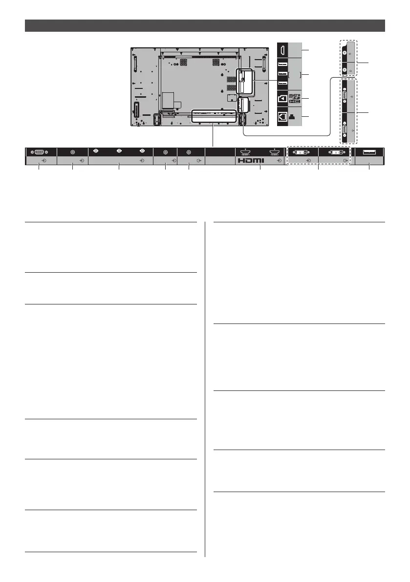
Video equipment connection
IR IN
SERIAL
OUT
IR OUT
SERIAL
IN
G/Y/VIDEO
B/P
B/CB
R/PR/CR
AUDIO1 IN AUDIO2 IN
COMPONENT/RGB/VIDEO IN
DVI-D IN DVI-D OUT
AUDIO OUT
USB
PC IN
AV IN
1 2 3 4 5 6 7 8
Micro-USB
USB
OpenPort
PLATFORM
LAN
11
12
13
14
9
10
1 PC IN: PC Input Terminal
Connect to video terminal of PC,
video equipment with “YP
BPR /
YCBCR” or “RGB” output.
(see page 23)
2 AUDIO1 IN: Audio input terminal shared
with DVI-D IN and PC IN
(see page 22, 23)
3 COMPONENT /
RGB /
VIDEO IN:
COMPONENT / RGB Video
Input Terminal (R/P
R/CR, B/PB/
CB, G/Y)
Connect to video equipment
with “YP
BPR / YCBCR” or “RGB”
output.
(see page 25)
Composite Video Input
Terminal (VIDEO)
Connect to video equipment with
Composite signal output.
(see page 24)
4 AUDIO2 IN: Audio Input Terminal shared
with COMPONENT/RGB IN and
VIDEO IN
(see page 24, 25)
5 AUDIO OUT: Analogue Audio Output
Terminal
Connect to audio equipment with
analogue audio input terminal.
(see page 28)
6 AV IN
(HDMI 1,
HDMI 2):
HDMI Input Terminal
Connect to video equipment such
as VCR or DVD player, etc.
(see page 21)
7 DVI-D IN,
DVI-D OUT:
DVI-D Input / Output Terminal
Connect to video equipment
with DVI-D output. Also, when
displaying the picture by daisy
chaining multiple displays,
connect to the other display
(DVI-D OUT).
The DVI-D output function is
enabled only when the picture is
displayed via DVI-D IN.
(see page 22)
8 USB: USB Terminal
Connect the USB memory to use
[USB media player]. Also, this
can be used to supply power of
up to 5V/1A to an external device
when the picture is displayed.
(see page 28)
9 IR IN, IR OUT: Infrared Signal Input / Output
Terminal
Use this when operating more
than one display with one remote
control.
(see page 28)
10 SERIAL IN,
SERIAL OUT:
SERIAL Input / Output Terminal
Control the Display by connecting
to PC.
(see page 25)
 Loading...