3.2 Device diagrams
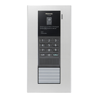
3.2.1 Lobby Station
Front view
A Heat sensor
Turns on the display when a visitor is detected.
B Lens cover
C Light
Illuminates subjects in dark environments.
D Display
E Keypad
F Speaker
G Camera lens
H Microphone
I
Search buttons (
and )
Used to select items shown on the display.
J
Cancel button ( )
K
Call button (
)
Rear view
ONOFF
V700 K-IN K-OUT
L1 L2 C1C2 S1 S2
H
I
J
A
G
F
B
C
D
E
A Reset button ( )
Used when restarting the lobby station.
B Function button ( )
For internal use only.
C Power switch
D Cable release button for DC power supply cable
E Connection terminals for power supply
F USB port
For internal use only.
G Coaxial connector for external camera
H Connection terminals (output) for electric lock (K-OUT)
Used to send signals to the electric lock.
I Connection terminals (input) for access controller (K-IN)
Used to receive signals from the access controller.
J Connection terminals for control box (V700)
12
3. Preparation

 Loading...