5
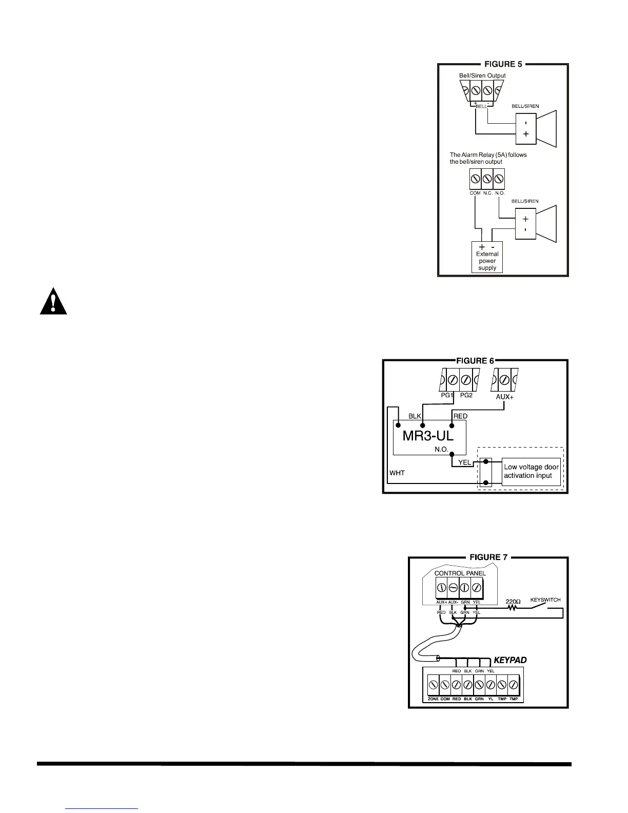
2.5 Bell/Siren Output
The BELL+ and BELL- terminals power bells and/or other warning
devices requiring a steady voltage output during an alarm. The bell
output supplies 12VDC upon alarm and can support two 20-watt or two
30-watt sirens. The bell output is microprocessor-controlled and will
automatically shut down if the current exceeds 3A. If the load on the
BELL terminals returns to normal (
?
3A), the control panel will re-instate
power to the BELL terminals. When connecting sirens (speakers with
built-in siren drivers) please verify correct polarity. Connect the positive
lead to the BELL+ terminal and the negative lead to the BELL- terminal
of the control panel as shown in figure 5. The Alarm Relay (optional),
which is rated at 5A, can also be used to power bells and/or other
warning devices requiring a steady voltage output during an alarm (see
figure 5). The Alarm Relay is activated (toggles to opposite state)
whenever the local bell/siren output is activated.
If the Bell/Siren output is not being used
when connecting a bell or siren to an optional relay
output, the [4] trouble indicator (see section 11.12.3) will always be on. To avoid this, connect a
1K
?
resistor across the bell output.
2.6 Programmable Outputs (PGM)
The Esprit “Plus” control panels include two fully
programmable output (PGM). When a specific event or
condition occurs in the system, a PGM can be used to
reset smoke detectors, activate strobe lights, open/close
garage doors and much more. The PGMs provide a
maximum 50mA output. If the current draw on a PGM
output is to exceed 50mA we recommend the use of a
relay as show in figure 6. The PGMs can be programmed
to toggle on and off from more than a thousand different
events. For example, PGM1 can open and close an
automatic garage door by pressing keys [1] and [2]
simultaneously on the keypad. For details on how to
program the PGMs, refer to section 9.
2.7 Keypad & Keyswitch Connections
Connect the four keypad connections labeled RED, BLACK, GREEN
and YELLOW to the corresponding colour terminals on the control
panel as indicated in figure 7. Note, on some keypads you may
have to remove the back panel to make the connections.
Connect the keyswitch to the “GRN” and “BLK” terminals of the
control panel as shown in figure 7. To enable this function
please refer to sections 8.5 and 11.8 for more information on
keyswitches.
2.8 Keypad Zone Connections
Each keypad comes with one input terminal, allowing you to connect one detector or door contact
directly to the keypad.
Installation
 Loading...