Parker Hannifin
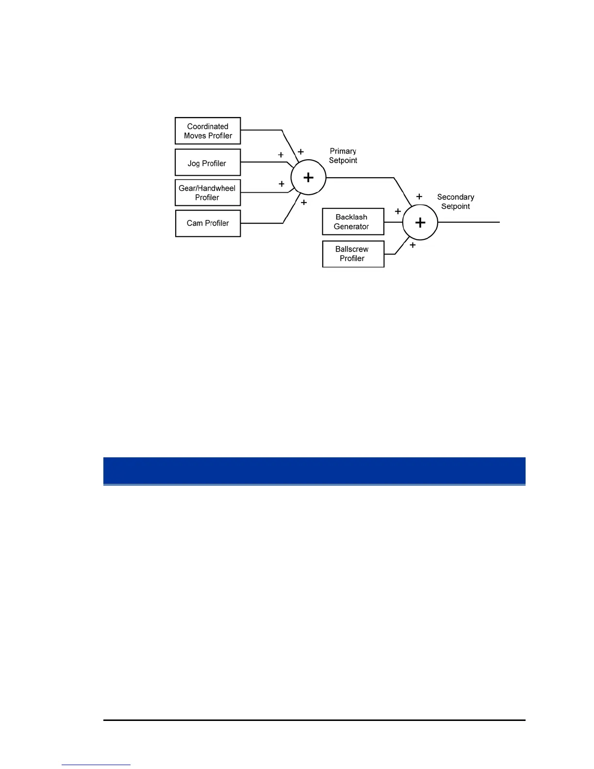
The information up to and including the SSP is the commanded
position. See Figure 16.
Figure 16 Secondary Setpoint Summation
Viewing the Setpoint Calculations
Servo loop calculations for the actual position of an axis can be
observed in ACR-View. The Servo Loop Status window shows the
motion offsets, primary and secondary setpoints, servo gains and
other values, and how they result in the final position output.
► In the Project Workspace, click Status Panel, then click Servo
Loop Status.
Following Error
The Secondary Setpoint is compared with the value of the Actual
Position received from a feedback device. See Figure 17. The
difference between the Secondary Setpoint and Actual Position is
called the Following Error:
Following Error = SSP - ACT POS
The controller makes adjustments to the motor position through a
constant cycle of comparison and correction. Following Error is used
by the PID loop (servo control algorithm) to keep the Actual Position
equal (or approaching equal to) the Secondary Setpoint.
88 Programmer’s Guide

 Loading...


