Parker Hannifin
194 ACR9000 Series Hardware Installation Guide
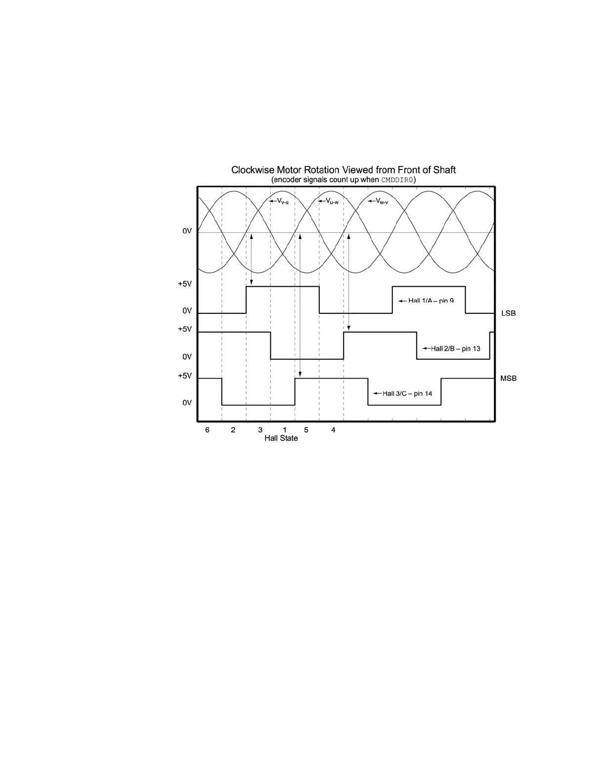
Figure 50 illustrates the alignment of phases U, V, and W with Halls 1, 2, and
3 as viewed from the front of the shaft. The illustration assumes the following:
Hall signals that are High equal
TRUE signals.
Hall 1 is the least significant bit (LSB).
Hall 3 is the most significant bit (MSB).
There is one hall cycle and one electrical cycle per pole pair on the motor.
Figure 50 Motor Terminal Voltages (back EMF) and Hall Sensor Signals
www.comoso.com
 Loading...


