HHAASS CCaabbllee CCoonnnneeccttiioonnss
MMoottoorr FFeeeeddbbaacckk CCaabbllee
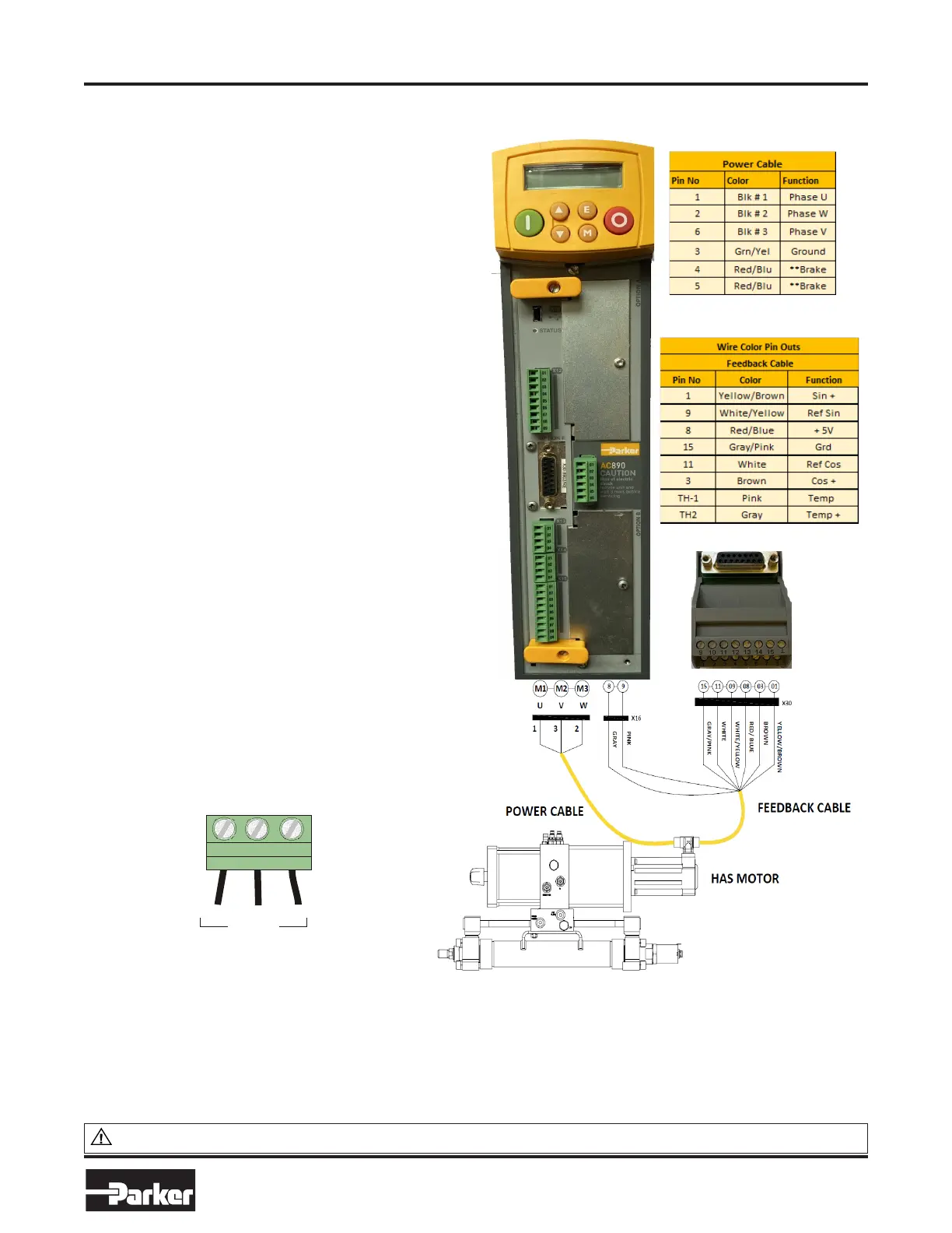
The default motor feedback for HAS A series motor is a Resolver.
This device is used to provide feedback of the motor speed to
provide closed loop control of HAS motor.
A Series Motors PS series connectors feature TE Connectivity
Interconnection circular connectors mounted to the motor body.
These connectors are right angle mount and can be fully rotated.
This allow greater cable routing options.
The supplied Feedback cable is a flying lead, 17 conductor cable.
Not all conductors are used.
Included in the HAS Drive Kit is a Sub DB15 breakout module and
mating 5 foot cable. This module features wire connection
terminations for the feedback cable, while allowing easy
connection to the Drive.
A series Motors are equipped with temperature monitoring sensor
and connections is located in the feedback cable. The break out
module allows the installer to connect the Pink and Gray wires to
connector X16, pins 8 and 9 located on the bottom of the drive. It
is also labeled as TH1, T2. Wire polarity does not matter.
The drives are shipped with a jumper connected X16 pin 8 and 9,
this jumper must be removed to thermally protect the motor from
overload condition.
MMoottoorr PPoowweerr CCaabbllee
The supplied power cable consist of a flying lead, 6 conductor
cable.
It is important to connect the U, V and W phase wires correctly. In
correct wiring will cause the HAS motor to lock up pulling full current
CCaabbllee WWiirree ## 11 ((UU)) ccoonnnneeccttss ttoo MM11 oonn ddrriivvee
CCaabbllee WWiirree ## 33 ((VV)) ccoonnnneeccttss ttoo MM22 oonn ddrriivvee
CCaabbllee WWiirree ## 22 ((WW)) ccoonnnneeccttss
ttoo MM33 oonn ddrriivvee
The default motor for options for HAS unit do not include a
brake assembly. HAS units use traditional hydraulic means for
load holding. The Brake actuation wires are located in the
power Cable. These wire have no connection and are not
needed. FFoollllooww GGrroouunnddiinngg pprraaccttiicceess lliisstteedd oonn ppaaggee 77
M1 M2 M3
MOTOR
M1 (U), M2 (V), M3 (W).
Maximum wire sizes:
Frame B: 6mm
2
/ 10AWG, 0.8Nm / 0.6ft-lbf
Frame C: 10mm
2
/ 8AWG, 1.7Nm /1.25ft-lbf
WWAARRNNIINNGG:: This product can expose you to chemicals including LLeeaadd aanndd LLeeaadd CCoommppoouunnddss which are known to the State of
PPRROOPP 6655 WWAARRNNIINNGG
California to cause cancer and birth defects or other reproductive harm. For more information go to www.P65Warnings.ca.gov
PPaarrkkeerr HHaannnniiffiinn CCoorrppoorraattiioonn
Cylinder Division
Des Plaines, Illinois
15
wwwwww..ppaarrkkeerr..ccoomm/
cylinder
•
CylindersHybrid Actuation
System SSeerriieess HHAASS 550000
Catalog HY08-
HHAASS CCaabbllee CCoonnnneeccttiioonnss

 Loading...


