EasyManua.ls Logo

Parker IPA Series User Manual

Parker IPA Series
128 pages
To Next Page IconTo Next Page
Page #1 background imageLoading...
Page #1 background image
Effective: December, 2014
Document Number: 88-032500-01A
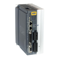
IPA Intelligent Parker Amplifier
Hardware Installation Guide

Table of Contents

Questions and Answers:

Parker IPA Series Specifications

General IconGeneral
Supply Voltage24 VDC
TypePAC
Input SignalAnalog and Digital
Feedback SignalAnalog
CommunicationEthernet
MemoryFlash and RAM
Communication PortsEthernet, USB, Serial
Programming LanguagesIEC 61131-3 (Ladder Diagram, Function Block Diagram, Structured Text)
Operating Temperature0°C to 50°C (32°F to 122°F)
CertificationsCE, UL

Summary

User Information

Contact Information for Technical Assistance

Provides contact details for Parker Hannifin technical support centers.

Important Safety Information

Chapter 1 Introduction

IPA Controllers—Overview

Overview of IPA single-axis drive/controller platform.

Input Power Level

Specifies the input voltage and power requirements for IPA models.

Checking Your Shipment

Lists items included with IPA drives and instructions for checking shipment.

Chapter 2 Mechanical Installation

Environment & Drive Cooling

Details operating temperature, humidity, and cooling requirements for IPA drives.

Cabinet Cooling

Explains how to calculate cabinet cooling and provides power dissipation tables.

Panel Routing

Specifies clearance requirements for panel mounting IPA drives.

Chapter 3 Electrical Installation

Installation Safety Requirements

Outlines safety requirements for IPA installation, including LVD and EMC directives.

Connectors

Identifies and locates the various connectors on the IPA drive.

X2 – Input Power / Mains Connector

Details the specifications and function of the X2 Input Power/Mains Connector.

Power Supply

Explains power supply requirements and connections for the IPA.

Separate Sources Connections

Illustrates connecting separate sources for motor and control power.

Chapter 4 Communications

Ethernet Specifications

Covers Ethernet cable and connector specifications.

Assigning IP Addresses

Details the process of setting IP addresses for the IPA and PC.

Chapter 5 Troubleshooting

General Troubleshooting Guidelines

Provides a general approach to troubleshooting IPA issues.

Power

Guides on troubleshooting power-related issues using status LEDs.

Error Codes

Lists common error codes and their resolutions.

Chapter 6 Torque Enable Safety Circuitry

Torque Enable Functional Description

Explains the dual-channel hardware implementation of the Torque Enable function.

Fault Operation

Describes fault detection when Torque Enable inputs are in opposite states for too long.

Chapter 7 Additional Specifications

Protective Circuits

Details the drive's protective circuits, including short circuit protection.

Under-Voltage Protection

Details the circuit that monitors AC input voltage for under-voltage conditions.

Current Foldback

Describes the circuit that protects against prolonged high currents.

Chapter 8 Regulatory Compliance UL and CE

System Installation Overview

Provides information on installation practices for regulatory compliance.

General Safety Considerations

Outlines safety procedures based on local regulations and IEC standards.

Appendix A VM25 Expansion Module

Overview

Introduces the VM25 Expansion Module and its features.

Appendix B IPA with IForce or Ripped Linear Servos

IForce/Ripped to IPA-Controller Wiring

Clarifies wiring connections for IForce/Ripped motors and positioners.

Software Configuration: Set Feedback Resolution

Details setting encoder feedback resolution in ACR-View.

Appendix C IPA with Parker Mechanics

Limit/Home Sensor Wiring

Shows wiring for limit/home sensors with connector box options.

Related product manuals