21
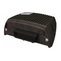
Connectors C1-C4
6 Installation
Instruction book, IQAN-MC3
6 Installation
Connectors C1-C4
Connector C1 pin assignments
Connector kit
Parker no. 5035016
a
a.Kit contains parts for all 4 connectors, C1 - C4
Housing Deutsch no. DT16-18SAK004
Pin types 1062-16-0644
Cables 0.75 mm² (18 AWG)
Plugs (empty pos.) Deutsch no. 114017
Deutsch crimping
tool reference
DTT-20-00
Prototype cable Parker no. 5030216
Symbol Pin
No.
In
Out
Function
-BAT 1 - Power supply GND
-BAT 2 - Power supply GND
CAN-A-L 3 - CAN low voltage bus line, will be LOW in dominant state.
CAN-A-H 4 - CAN high voltage bus line, will be HIGH in dominant state.
CAN-B-L 5 - CAN low voltage bus line, will be LOW in dominant state.
CAN-B-H 6 - CAN high voltage bus line, will be HIGH in dominant state.
ADDR-L 7 - IdTag interface. Low side to address tag. Return signal.
ADDR-H 8 - IdTag interface. High side to address tag. Sourcing +5V.
CAN-C-L 9 - CAN low voltage bus line, will be LOW in dominant state.
CAN-C-H 10 - CAN high voltage bus line, will be HIGH in dominant state.
CAN-D-L 11 - CAN low voltage bus line, will be LOW in dominant state.
CAN-D-H 12 - CAN high voltage bus line, will be HIGH in dominant state.
+BAT 13 - Power supply 12/24 Vdc
+BAT 14 - Power supply 12/24 Vdc
DOUT-D 15 O DOUT power driver (type B), high side
DRET-D 16 O DOUT power driver (type B), low side
DOUT-E 17 O DOUT power driver (type B), high side
DRET-E 18 O DOUT power driver (type B), low side

 Loading...


