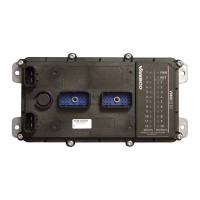
In the event of a fault, the VMM1210 will disable the output(s) that are
faulted. The automatic recovery of faulted states can be turned on or off
(for safety reasons). If it is turned on, the automatic fault retry can be
adjusted to suit a variety of safety related situations.
Open load detection allows for the detection of open (burnt out) loads, this
detection can be turned on or off and can also be modified to check only at
power up of the system or continuously.
Over current levels can be adjusted in one amp increments anywhere from
1A to 12A to allow the system to react more like various fuse types.
Communicate Input/Output State Information:
In order to multiplex, the VMM1210 must be able to communicate its
information to other CAN/J1939 based equipment in the vehicle. The
VMM1210 does this by transmitting J1939 messages representing the
states of its inputs and outputs and other ladder logic based equipment.
These messages are broadcast type and can be read by and acted on by any
other module connected to the same CAN/J1939 network.
Processes Ladder Logic:
Ladder logic is a graphical representation of standard logic (AND, OR,
NOT, etc). The VMM1210 processes ladder logic written using the
Vansco Multiplex Module Software package (VMMS). The ladder logic
defines which inputs or arrangement of inputs turns on which outputs on
the module. The inputs and outputs in the ladder logic can be from one or
more modules connected together in a system via the CAN/J1939
network. For more information on the VMMS package, please refer to the
VMMS User Guide, or the VMMS help files for information.
1.1. Diagram conventions
The following symbols are used in the schematic diagrams in this document:

 Loading...


