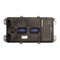
5.1.2. Logic and Output Power Connections
When connecting the VMM1210 logic power, note that
Logic power connections are made using the VBATT_LOGIC and GND pins.
The VMM1210 is protected against reverse-battery connections by an internal
high-current conduction path that goes from ground to power. To protect the
VMM1210 from damage in a reverse-battery condition, place a fuse of 1 A or
less in series with the power wires in the application harness.
Note: Reverse-battery protection is only guaranteed when using standard
automotive fuses.
Select fuse sizes by multiplying the maximum continuous current during normal
operation by 1.333 (75% de-rating factor). Do not use slow-blow fuses for this
application.
All power connections to the VMM1210 should be fused to protect the vehicle
harness.
5.2. Busbar Power
There are two main power connections for the high current bus bar battery power
inputs (BUSBAR1 and BUSBAR2). The busbar inputs are separated into two
connectors (J1 and J2).
5.2.1. Busbar Power Capabilities
Busbar power provides power to the output circuits through a battery or ground
connection. Each busbar circuit can draw a maximum of 40 A.
The following table provides specifications for the VMM1210 busbar power:
5.2.2. Busbar Power Installation Connections
Connectors J3 and J4 provide power to Busbar 1 and Busbar 2 respectively, and
are required if the outputs that get power from those busbars are used.The busbar
power lines (J3-A/J3-B and J4-A/J4-B) are connected to 12 Vdc or 24 Vdc.

 Loading...


