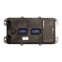
There are two pins on each of J3 and J4, these are internally connected on the
VMM1210. Both pins on J3 and/or J4 need to be connected if the current flowing
through an individual busbar exceeds 20A. It is recommended that the busbar
power wires be kept on a dedicated high current power connection point, isolated
from the logic power wires where possible.
The system VBATT_LOGIC (logic power) line (J1-1A) is connected to 12 Vdc or
24 Vdc. The system GND (logic ground) line (J1-3A) is connected to ground. It is
recommended that the logic power and ground wires be kept isolated from high
current power and ground studs where possible. This will prevent dips in the high
current lines from affecting the logic power and ground signals at the VMM1210.
Busbar power connections in a system may be made using a ground cable or
chassis ground. Examples of both are shown in the figures below.
Proper fusing is required on any power wires coming off of the battery
terminal. This fusing is not shown in the following figures.

 Loading...


