Publication History .............................................................................................................. vi
Safety ................................................................................................................................... vii
Safety symbols ................................................................................................................................ vii
General safety regulations .............................................................................................................. vii
Welding after installation ................................................................................................................ viii
Construction regulations ................................................................................................................ viii
Safety during installation ................................................................................................................ viii
Safety during start-up ....................................................................................................................... ix
Safety during maintenance and fault diagnosis ............................................................................... ix
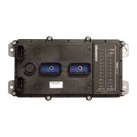
1. About the VMM1210 .......................................................................................................... 1
1.1. Diagram conventions ................................................................................................................ 2
2. Quick Start ......................................................................................................................... 5
2.1. Overview ................................................................................................................................... 5
2.2. Gather Required Materials ........................................................................................................ 5
2.3. Install the Required Software Tools .......................................................................................... 6
2.3.1. Install the Data Link Adapter Driver Software ............................................................. 6
2.4. Connect the VMM1210 multiplexing module to a Development System .................................. 7
2.4.1. Power Up the Development System ........................................................................... 8
2.5. Create and Download Ladder Logic Applications ..................................................................... 9
3. Inputs ............................................................................................................................... 10
3.1. Programmable Digital Input Types .......................................................................................... 10
3.1.1. VMM1210 Programmable Digital Inputs .................................................................... 10
3.1.2. Power Control Digital Inputs ...................................................................................... 13
3.2. Addressing Digital Inputs ........................................................................................................ 14
3.3. Programmable Multi-Purpose Inputs ...................................................................................... 15
3.3.1. Multi-Purpose Used as Analog Input ......................................................................... 15
3.3.2. Multi-Purpose Used as Digital Input .......................................................................... 18
3.3.3. Multi-Purpose Used as DC-Coupled Frequency Input .............................................. 20
4. Outputs ............................................................................................................................ 23
4.1. 10 A High-Side Outputs .......................................................................................................... 23
4.1.1. High-Side Output Capabilities ................................................................................... 23
4.1.2. High-Side Output Configuration ................................................................................. 24
4.1.3. High-Side Output Installation Connections ................................................................ 25
4.2. 3 A High-Side/Low-Side Outputs ............................................................................................ 26

 Loading...


