3.1.1.2. Programmable Digital Input Configuration
Digital inputs are configured as active high or active low by using pull-up or pull-
down resistors internal to the module.
When the input is configured as active high, an internal pull-down resistor is
used, and the input will be active when it is switched to battery voltage.
When the input is configured as active low, an internal pull-up resistor is used,
and the input will be active when it is switched to ground.
3.1.1.3. Programmable Digital Input Installation Connections
A digital input is typically connected to a switch that is either open or closed.
When the switch is open, the pull-up or pull-down resistor will ensure that no
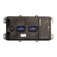
signal exists on the input pin, which will be interpreted by the VMM1210 as
inactive.
When the switch is closed, the input is connected to either battery voltage or
ground, which will be interpreted by the VMM1210 as active.
Active-high input
The active-high output must be connected to battery power to ensure that there is
a battery connection when the state of the input changes.

 Loading...


