PAGE 13
Wiring Connections 2.6
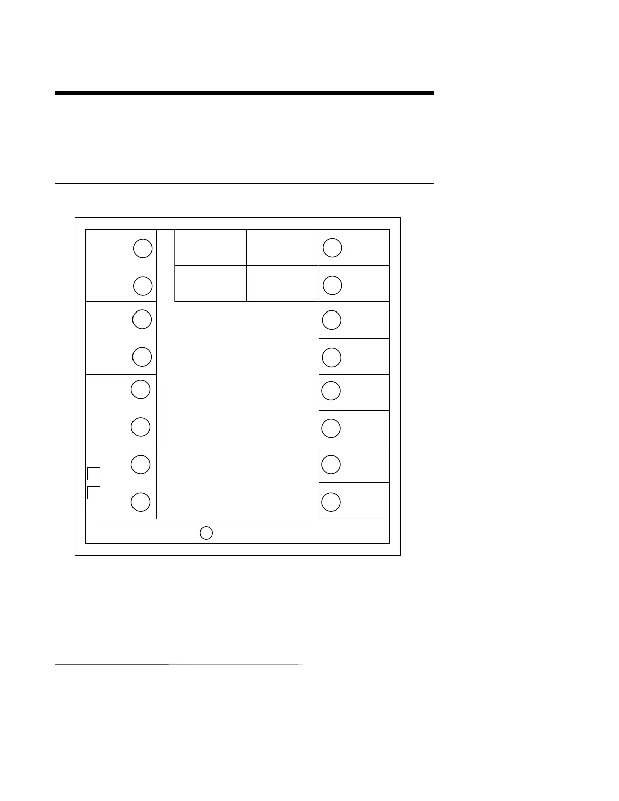
All wiring connections are typically made to the instrument with it installed. Terminal connec-
tions should be made via the rear panel with 14 gauge wire maximum (see Figure 2-4).
FIGURE 2-4
2.6.1 INPUT CONNECTIONS
WARNING: Avoid electrical shock. AC power wiring must not be connected at the source distribution panel until all wiring
connections are completed.
Consult the model code and the wiring label for the appropriate line voltage for the instrument.
1
2
3
4
D
C
B
A
RELAY A
115
230
VAC
SIGNAL +
CJC
SIGNAL -
MADE IN U.S.A.GROUND
INPUT RATINGS:
115/230 VAC 50/60 HZ 15VA MAX
RELAY OUTPUT RATINGS:
115VAC 5.0A RESISTIVE
230VAC 2.5A RESISTIVE
230VAC 1/8 HP
115/230VAC 250VA
MAXIMUM AMBIENT: 55˙C
SERIAL A
SERIAL B
POS. PROP.
WIPER
POS. PROP.
HIGH
OUT2
4-20MA
+
OUT1
4-20MA
+
RETURN
5
6
7
8
E
F
G
H
RELAY B
RELAY C
REMOTE
RUN/
HOLD