PAGE 15
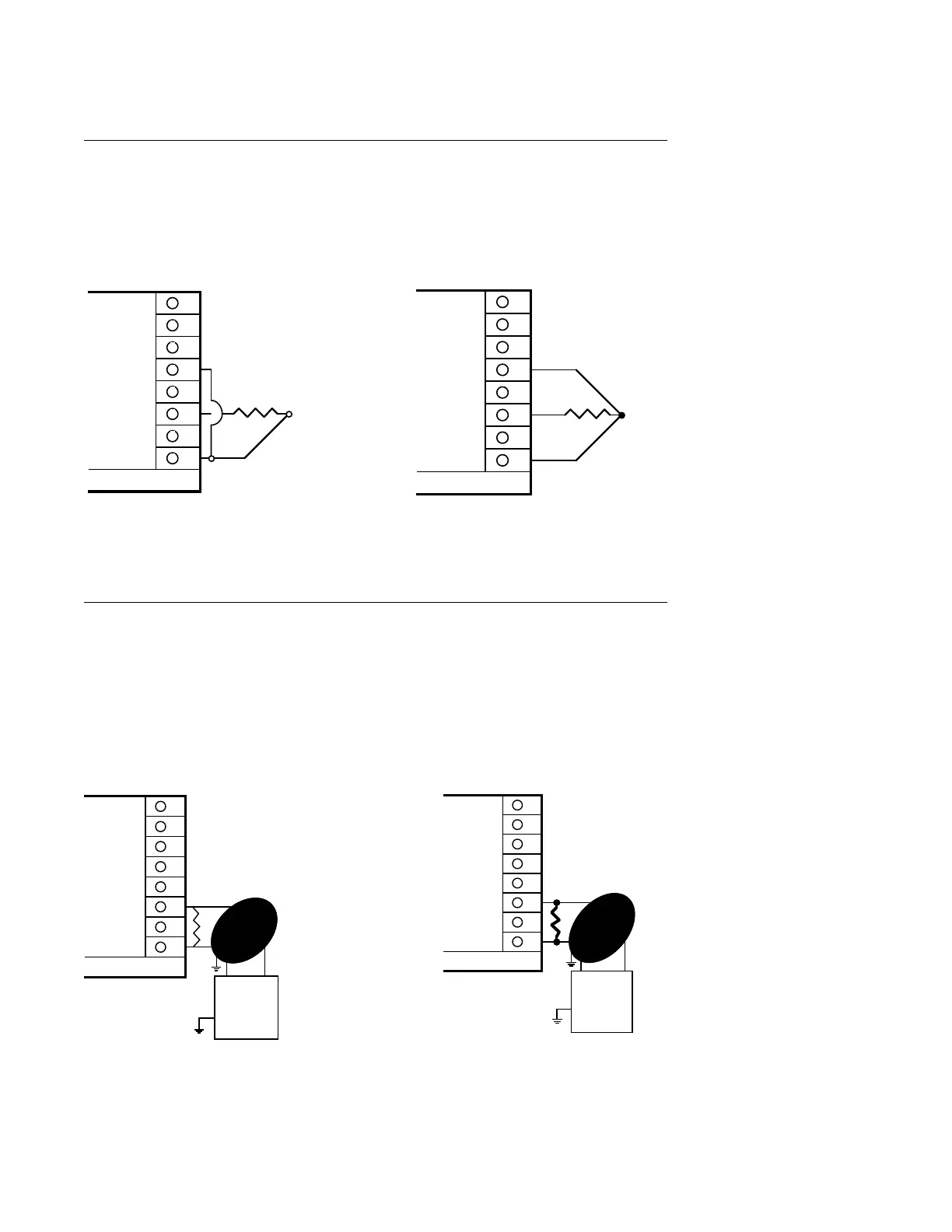
FIGURE 2-7
RTD Input
Connections are shown for 3 wire and 2 wire RTD's. If a three wire device is used, install the
common wires to terminals 1 and 5. If a two wire device is used, install a jumper between
terminals 1 and 5.
FIGURE 2-8
Volt, Millivolt and Milliamp Input
Make volt, millivolt or milliamp connections as shown below. Terminal 3 is positive and
terminal 1 is negative. Milliamp input requires a shunt resistor be installed across the input
terminals as shown. 4-20mA input are accommodated by setting up the instrument for either
10 to 50mVDC or 1 to 5VDC input. Make sure that the appropriate resistor value is used.
Terminal 3 is positive and terminal 1 is negative. (.1% resistors recommended.) (Continued
on next page)
8
7
6
5
4
3
2
1
2 WIRE RTD INPUT
100 OHM*
PLATINUM
10 FEET
LEAD
MAXIMUM
JUMPER*
Rear View
*Supplied by customer
100 OHM*
PLATINUM
8
7
6
5
4
3
2
1
3 WIRE RTD INPUT
Rear View
*Supplied by the customer
8
7
6
5
4
3
2
1
MILLIAMP DC INPUT
+
-
MILLIAMP DC
SOURCE
250 OHM SHUNT
RESISTER
REQUIRED
Rear View
Shielded Twisted
Pair
8
7
6
5
4
3
2
1
MILLIAMP DC INPUT
+
-
MILLIAMP DC
SOURCE
2.5 OHM SHUNT
RESISTER
REQUIRED
Rear View
Shielded Twisted
Pair
NOTE: Fault detection is not functional for 0-5 V or 0-20 mA inputs.