PAGE 42
4.1.2.7 POSITION PROPORTIONING CONTROL
Position Proportioning control can be implemented on those controllers provided with two
SPST relay outputs or two SSR Driver outputs and Slidewire Feedback option.
Positioning proportioning control permits the use of PID control where the final control
element is a modulating device such as a motorized valve. In this form, each of the two
required relays or SSR Drivers will be used to control the valve. One output is used to open
the valve, the other is used to close the valve. The slidewire feedback is used to provide a
signal relative to the valve armature position to the instrument.
As with the other proportioning control forms, the process input, tuning parameters and the
setpoint are used by the control algorithm to calculate the output % requried to correct for the
deviation between setpoint and process.
With Position Proportioning control, it may be necessary to adjust the Sensitivity (SEnS) Tune
mode parameter to reduce or eliminate oscillations of the motor around setpoint. If oscillation
occurs, increase the SEnS value until the motor stops oscillating. If the differential between
the Open and Closed rotation is too large, then decrease the SEnS value. Also, for proper
Position Proportioning operation, it is necessary to specify the actuation time of the valve or
damper from full open to full closed. If the motor has a stroke duration of 60 seconds, change
the value in the Cycle Time parameter Ct1 to 60. This ensures that the controller will move
the motor for the proper amount of time when making adjustments.
4.1.2.8 DUAL OUTPUT CONTROL
Dual output control can be performed when two outputs are specified. The outputs may be
programmed for On-Off, Time Proportioning, or Current Proportioning, as applicable.
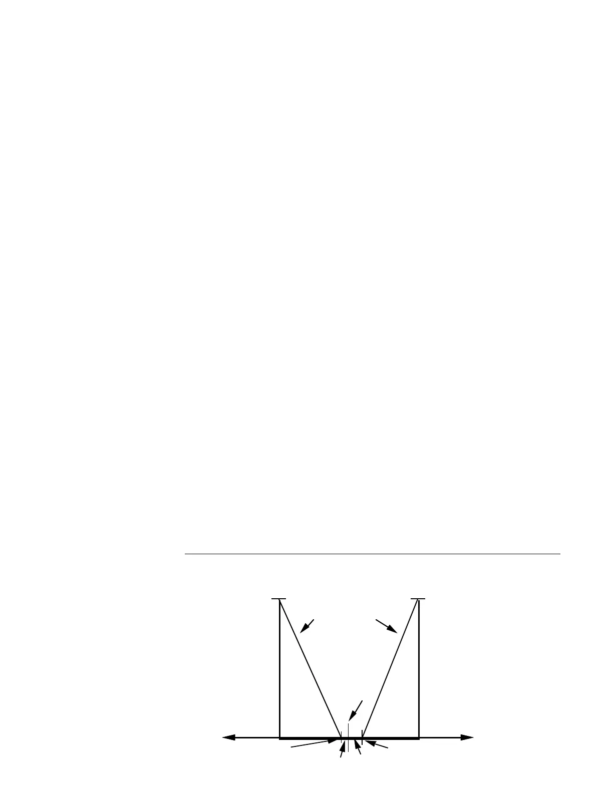
The output action is dependent upon the setpoint, the process value, and Tune mode
parameters. If two proporitonal outputs are selected, both output proportional bands will be
biased so that 0% of output is seen when the process value equals setpoint. The output(s)
can be biased by the use of the Tune mode parameters FOP and SPrd as shown in
Figure 4-1 (below).
The first output is programmed as a proportional reverse output and the second as a propor-
tional direct output. (See Glossary, page 67, for definitions of these terms). Dual proportion-
ing outputs are provided with separate proportional bands and cycle time
adjustments for each output.
FIGURE 4-1
100%
Proportional
Output 1
Reverse
Actin
Output
Direct
Actin
Output
100%
Proportional
Output 2
Control
Setpoint
First
Output
Position = X
Process
Value
+Y
-X
Second
Output
Position = Y