DATASHEET
α
6
Tips
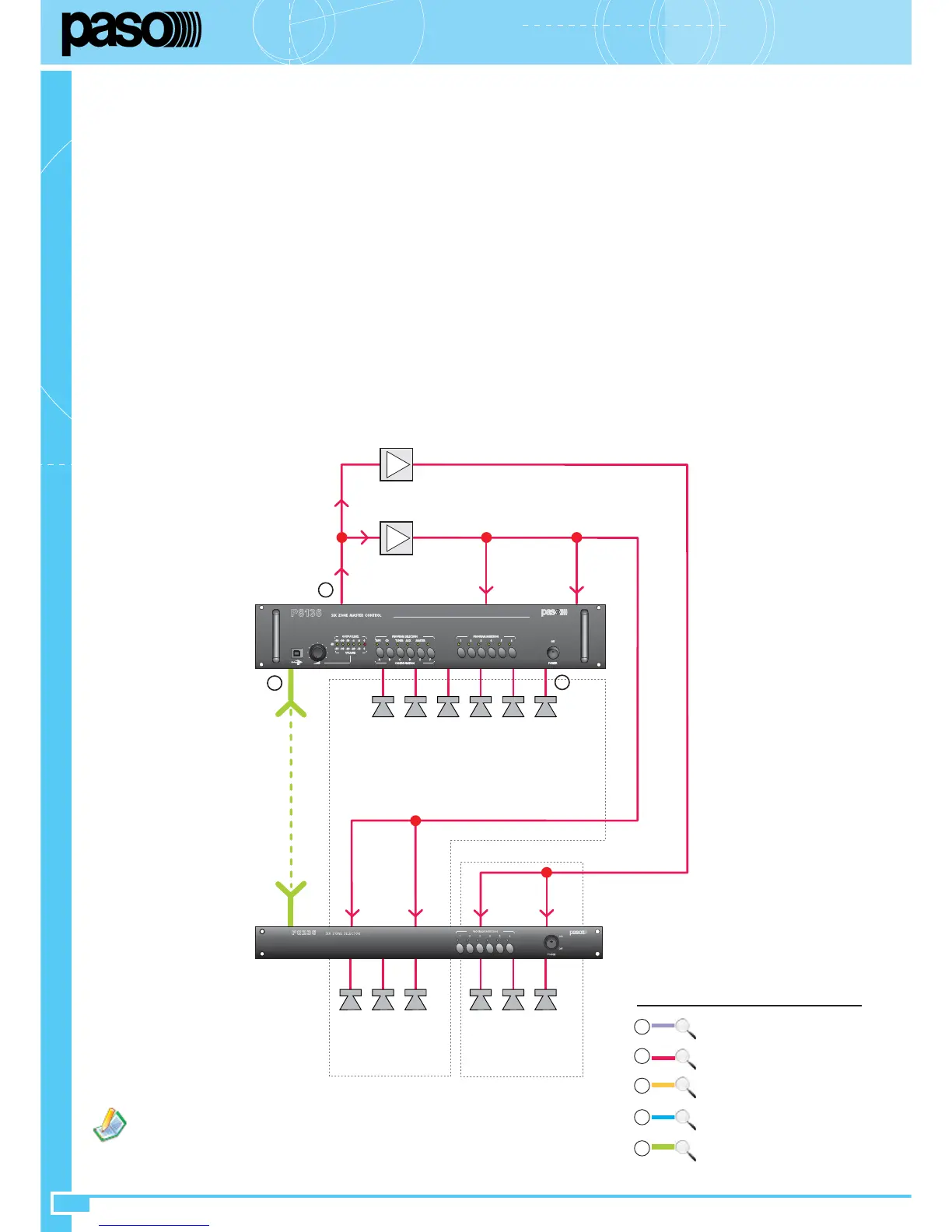
• If an overall output power exceeding that of a 500W amplifier (the largest in the Paso range) is required, it is possible to use more than one
amplifier. The inputs should be connected in parallel to the MIX OUT output (27) of the slave unit with the address 0; the output of each amplifier
will be used to drive a sub-group of zones having an overall output power compatible with the rated power of the amplifier. To facilitate this solution,
the 6 output zones of the slave are split up into two groups of 3, electrically isolated from one another and each with its own speech and music
inputs. This makes it possible to use up to two amplifiers per slave. An example of this type of system is illustrated in the figure.
System settings
Select the addresses of the
slaves
starting from 0 (considering also the one contained in the P8136).
Set the group number at 0 for all the
slaves
.
Set the operating mode of all the slaves – including the one contained in the P8136 – to single (see APPENDIX, Section A - page 18).
Activate/de-activate the CHIME function on the slave with the address 0 as required.
Connect the ACIO8136 cards, set to the Master mode, and the PMB stations to the TO MASTER UNITS socket (24). Set the addresses and
priorities as required, as indicated in section 4.
Note: Keep in mind that on the ACIO8136 Master cards, each input can have a different priority
(priorities to be set by means of the P8136 Manager configuration software)
.
Connect the ACIO8136 cards, set as Slaves and in the required operating mode, and the PMB stations to the TO SLAVE UNITS socket (30).
Set the addresses and priorities as required as indicated in section 4.
Note: Keep in mind that the ACIO8136 Slave cards have a fixed priority
level of 5
.
Set the MIX OUT (27), MUSIC OUT (26) and CHIME (31) controls to the minimum. First of all adjust the MIX OUT control (27) to the
required call sound level.
Adjust the CHIME control (31) (if this function is not activated, it is preferable to leave the control on the minimum level).
1.
2.
3.
4.
5.
6.
7.
8.
If background music is not provided, it is not necessary to cable
the terminals M. (18) and (23) of the panels.
SPEECH / MUSIC 240W
A
A
SPEECH / MUSIC 500W
IN M. IN SP
MIX
OUT
6 X 40W
LINK
IN
1÷3
M
IN
1÷3
SP
IN
4÷6
M
IN
4÷6
SP
3 X 80W 3 X 80W
Z... Z... Z... Z... Z... Z...
P8136
Z1 Z2 Z3 Z4 Z5 Z6
P8236
5
2
2
Local
units connection
Master
units connection
Master/Slave connection
3
Amplifiers/Loudspeakers connection
2
4
Music sources connection
1
5
See
APPENDIX, Section B