DATASHEET
P8136
9
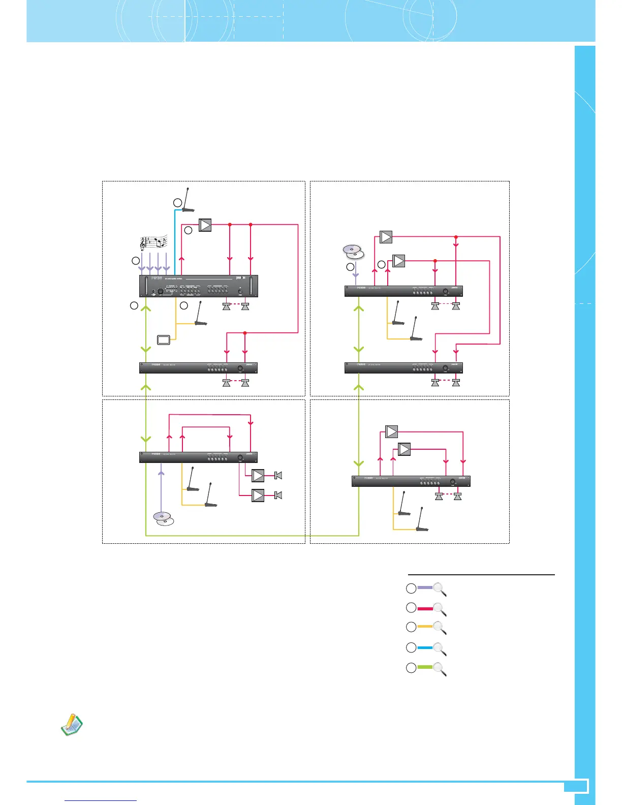
5.4 System with amplification according to multiple groups
This configuration is an application of the 3 illustrated above in sections 5.1, 5.2 and 5.3, showing that it is possible to size the system depending on
a number of needs:
• splitting up the installation physically into a number of sub-systems at sites at a distance from one another;
• creating sub-systems with local call stations;
• optimising the use of amplifiers on the basis of the requirements of the system and of the power of the various different zones;
The diagram illustrates an example of system split up into four sub-systems or groups:
- The sub-system A, group 0 (12 zones), consists of the master/slave set with the addresses 0 and 1.
- The sub-system B, group 1 (6 zones), consists of the slave with the address 2.
- The sub-system C, group 2 (12 zones), consists of the slaves with the addresses 3 and 4.
- The sub-system D, group 3 (6 zones), consists of the slave with the address 5.
In the example, it is possible to note the following system features:
• A master system can be made up of several sub-systems of different types
• The local stations can make calls to all the zones in the group to which they belong (if
permitted by the number of selection keys).
• Local stations belonging to different groups can make calls at the same time within their
own groups, regardless of their priorities.
Sizing
For the sub-system of group 0, follow the indications provided in section 5.1.
For the sub-system of group 1, follow the indications provided in section 5.3.
For the sub-systems of groups 2 and 3, follow the indications provided in section 5.2.
Those slave units that share the signal of the same SPEECH amplifier or of the same MIX
OUT output (27) on their Speech inputs (17-22) MUST NECESSARILY be set in the
same group. The local stations in each group must be connected only to the slave unit
with the lowest address (group leader).
It is possible to use the SLAVE LINK interconnections (33) to create a system with several call groups sharing the music channel of the same
source, connected to the master.
On the other hand, it is possible to use the single MUSIC IN inputs (25) of each slave unit to connect different sources of music to each
slave, even if they belong to the same call group. This configuration is only permitted for systems in the DUAL mode, connecting the MUSIC
inputs (18-23) suitably to their respective music channel amplifiers or to their respective MUSIC OUT outputs (26) or their slave units (for
details see the section “Connection of music sources – Cutting off the music signal from the Slave Link connection” in the APPENDIX).
IN M. IN SP
Z7 Z12
P8136
LINK
ACIO8136
LOCAL UNITS
Z1 Z6
IN M. IN SP
LINK
P8236
Z25 Z30
IN M. IN SP
Z36Z31
IN M. IN SP
P8236
MIX
OUT
A
SPEECH / MUSIC
MUSIC
IN M. IN SPMIX
OUT
SPEECH
LOCAL UNITS
Z13
P8236
MUSIC IN
IN M. IN SPMIX
OUT
LOCAL UNITS
Z24Z19
P8236
MUSIC IN
MUSIC
A
A
SPEECH
P8236
LINK
LINK
3
A
Z18
A
MIX
OUT
MUSIC
A
A
SPEECH
LOCAL UNITS
A
B
C
D
Address M:
Address S:
Group:
mode
0
0
0
SINGLE
Address S:
Group:
mode
1
0
SINGLE
Address S:
Group:
mode
2
1
DUAL
Address S:
Group:
mode
5
3
DUAL
Address S:
Group:
mode
4
2
DUAL
Address S:
Group:
mode
3
2
DUAL
MUSIC
OUT
MUSIC
OUT
MUSIC
OUT
MASTER UNIT
(zones 1÷36)
1
1
2
2
45
Local
units connection
Master
units connection
Master/Slave connection
3
Amplifiers/Loudspeakers connection
2
4
Music sources connection
1
5
See
APPENDIX, Section B