DATASHEET
α
24
Appendix
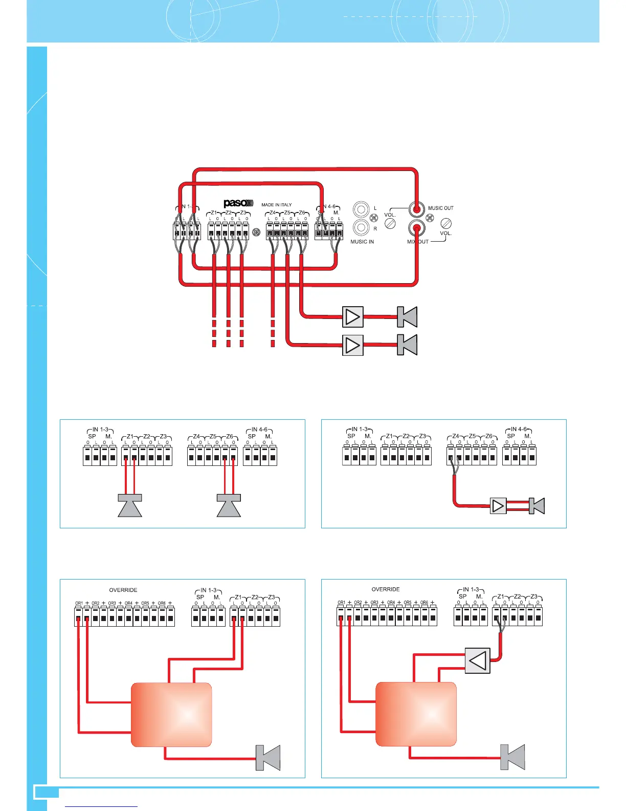
• System with dedicated amplification for each zone (see point 5.3)
Connect the MIX OUT output socket (27) in parallel to terminals SP (17) and (22), then onnect the MUSIC OUT output socket (26) in parallel to
terminals M. (18) and (23).
Use shielded cables and observe the signal polarities:
• The signal on the L terminal
• The shield on the 0 terminal
The signals to be sent to the inputs of the amplifiers are taken from the zone (19) and (21) output terminals.
Use shielded cables and observe the signal polarities:
• The signal on the L terminal
• The shield on the 0 terminal
To the zone amplifers
• Speaker units and override controls
For the cases referred to under points 5.1 and 5.2, the speaker unit lines are connected to the zone outputs of the panel using terminal strips
Z1 to Z6 (19) and (21). Pay attention when connecting the line to observe the correct polarities 0 (0V) and L (100V, 70V or 50V) in order to
maintain the correct phases of the speaker units. Consult the specific instructions for the speaker units used when making the connections.
For the case referred to under point 5.3, the speaker unit lines are connected directly to the power outputs of their respective zone amplifiers.
The 24 VDC controls for activating the by-pass relays of the volume controls for the speaker units are available on the OVERRIDE terminal
strip (15), and replicated in parallel on the RJ45 socket (16). These controls are active for their respective zones subject to calls for enabling
broadcasting of messages, always at the highest possible level. By way of example, the figure below shows the connection diagram of a control
on Zone 1. The output voltages are protected by a resettable fuse. The maximum capacity of each of the 6 outputs is 100mA.
Section BConnections (2)
Ref. par. 5.1/5.2 Ref. par. 5.3
Ref. par. 5.1/5.2 Ref. par. 5.3
OUT
OUT
BOOSTER
IN
IN
BOOSTER
100V
0V
100V
0V
+
-
100V 0V
IN
OUT
L 0V
24V
Relè
0V
Z1
IN
OUT
BOOSTER
+
-
100V 0V
IN
OUT
L 0V
24V
Relè
0V
Z1
IN
BOOSTER
0 V
100 V