LED signal Function / Meaning
LED light strip display
L1 ... L7
No LED ≙ fan speed 0 (fan off, standby)
1 LED (L1) ≙ fan speed 1
2 LEDs (L1 + L2) ≙ fan speed 2
... etc.
7 LEDs (L1+ L2+…+ L7) ≙ fan speed 7
No external release: fan is off
Supply and extract air mode
L8 blinks Error (sensor or frost protection (outdoor air temperature too low)):
L8 + L10 blink
Summer ventilation temperature limit configuration mode
(Displayed only during the configuration phase)
General error, the error number is displayed binary with the LEDs L1 to L7 (see
Table 38 in chapter 5.8.1 error signals with LED control panel)
L8 + L12 light up + L11 blinks 2x
and then stays out
Configuration mode for operation together with a fireplace
(Displayed only during the configuration phase)
Boost ventilation mode (L1 + L2 + L3 + L4 + L5 + L6 + L7 light up)
Filter running time expired
The remaining filter running time is ≤ 10 days
Configuration mode balance compensation for the selected fan speed
(Displayed only during the configuration phase)
Error fan 1 HALL: Fans are switched off
L11 blinks briefly 3 times Extract air mode deactivated (extract air mode key locked, configuration for
operation in conjunction with fireplace active)
Error fan 2 HALL: Fans are switched off
Table 3: Functions assigned to LED signals
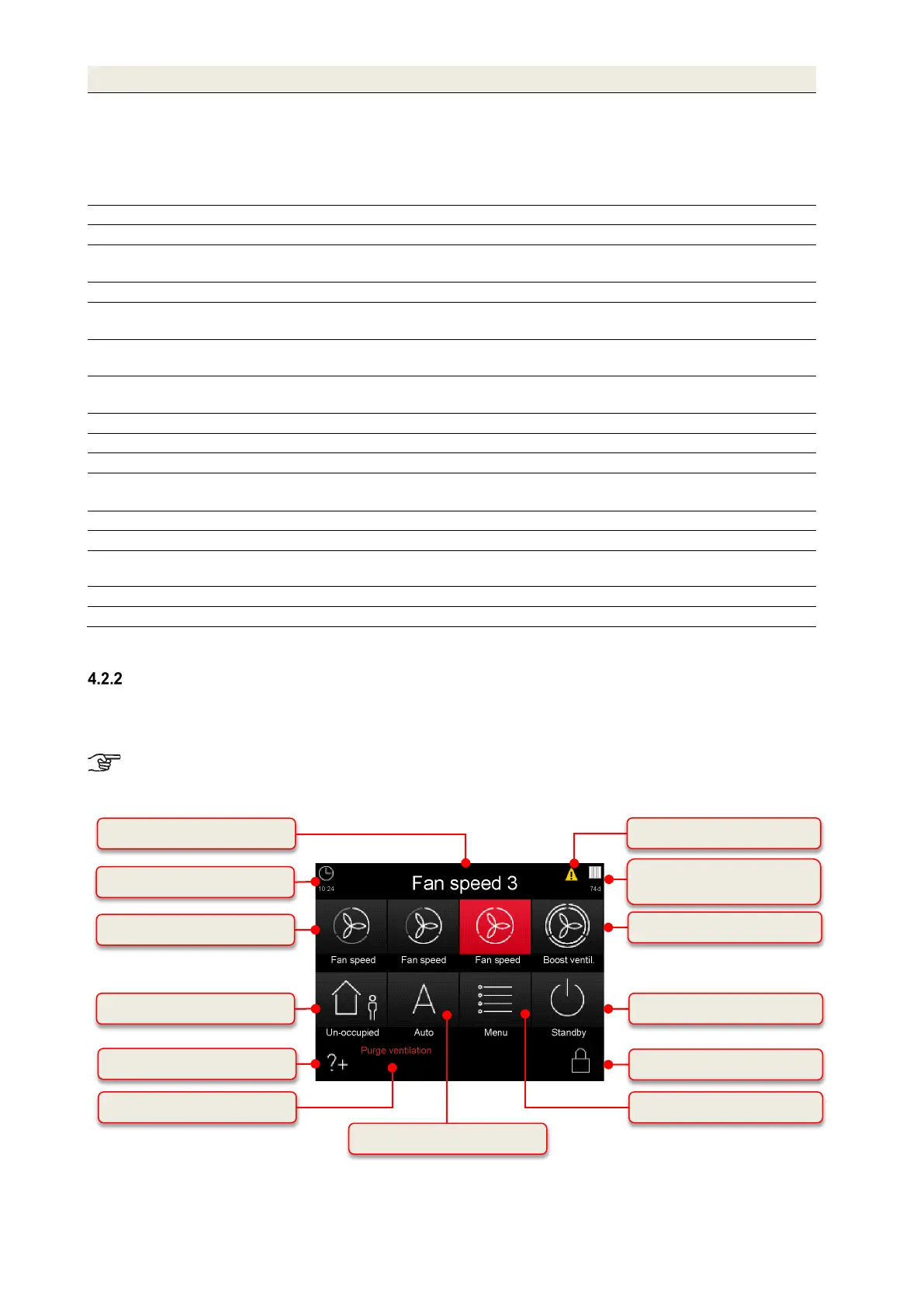
TFT control panel
The 3.5“ TFT display of the control panel is operated by touching the button symbols with the fingers. The active
operating mode and the associated button are indicated by colour signals. The control panel can be fitted into a
standard flush socket.
The ventilation unit can be operated with up to three TFT control panels or without a control panel. In
this case, the system operates in the last set operational mode.
Button for un-occupied mode
Filter symbol/filter running time
display
Button for boost ventilation mode
Button fan speed 1 – 2 – 3
Button for automatic mode
Active operating mode display
4: Operation and information fields of the touch pad