Master Controller X1 terminal Wire of boost ventilation key cable
Table 22: Terminal assignment of boost ventilation key connection
Connecting external sensors
The operating mode Automatic sensor of the automatic mode is controlled by an analogue sensor signal that is
generated by one or several sensors. To establish the connection between the sensor module and Master Controller
terminal X2, use the type of cable stipulated for transmitting the sensor signal. The cable is inserted into the FOCUS
through one of the pre-cut cable guides.
Master Controller X2 terminal Sensor module cable wire
Wire 1(sensor signal 0–10 V or 4–20 mA)
Table 23: Terminal assignment of analogue sensor signal connection
Connecting the status relay
A status relay on the Master Controller signals the operating status of the fans (factory setting).
Fan off: contacts open
Fan on: contacts closed
Master Controller X1 terminal Contact designation
Status relay make contact (max. 24 V switching voltage)
Status relay two-way contact (max. 24 V switching voltage)
Table 24: Terminal assignment of status relay connection
Connecting external release
The operation of the system can be activated or deactivated by an external release signal. The potential-free release
contacts are located next to the terminal X1 and are bridged ex-factory.
Master Controller X1 terminal Contact designation
Table 25: Terminal assignment of external release connection
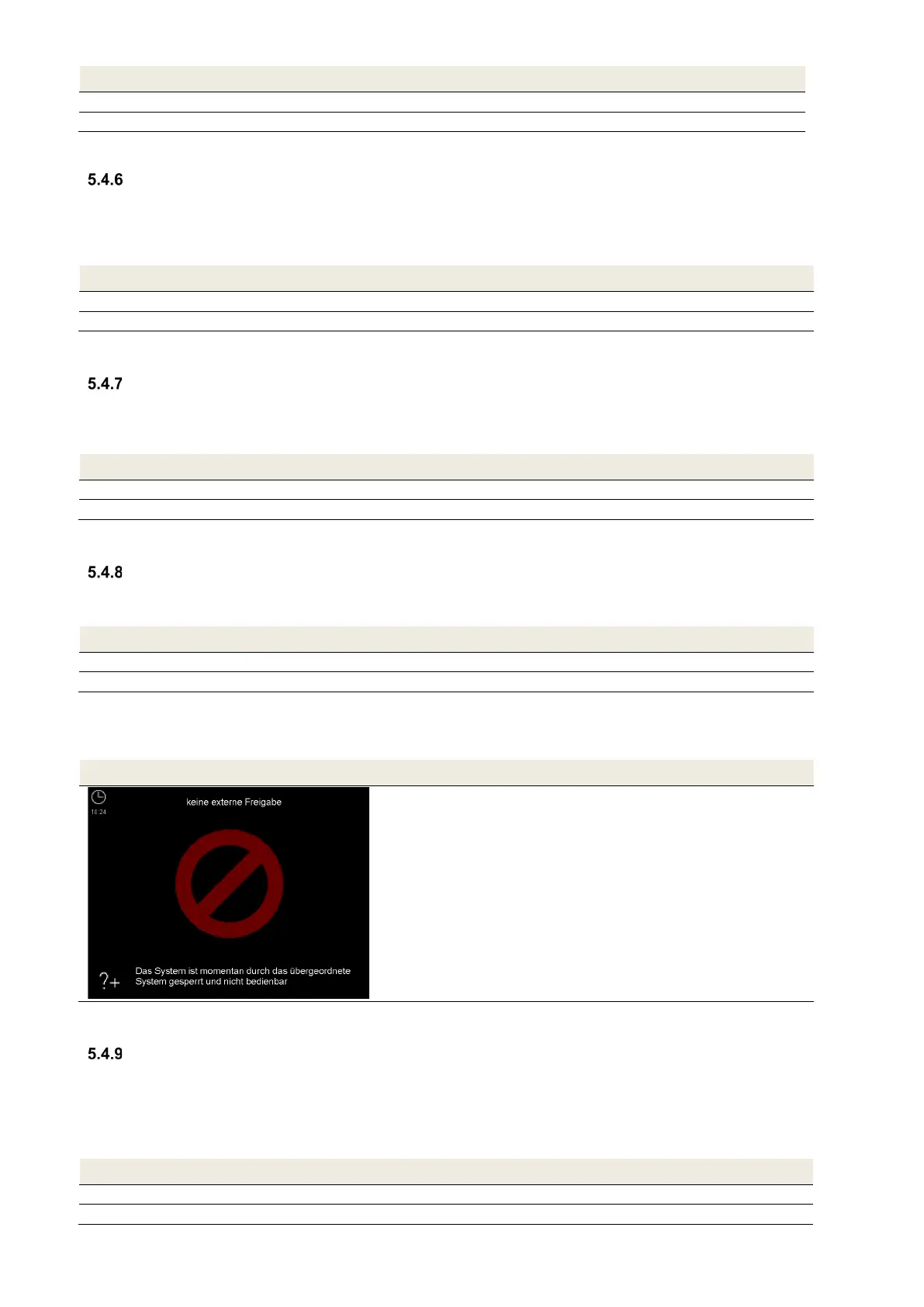
When the bridge is removed and there is no external release, the following displays are generated:
TFT control panel LED control panel
Table 26. Display of no external release
Connecting digital inputs and outputs
The digital inputs and outputs DIO1 and DIO2 can only be programmed with the configuration software. At the
factory, the following parameters are specified:
DIO1: Activate automatic (as a digital input signal)
DIO2: General message (as a digital output signal)
Master Controller X2 terminal Contact designation
Digital input or output 1 (can be parametrised)
Digital input or output 1 (GND)