18
9. HYDRAULIC SCHEMES
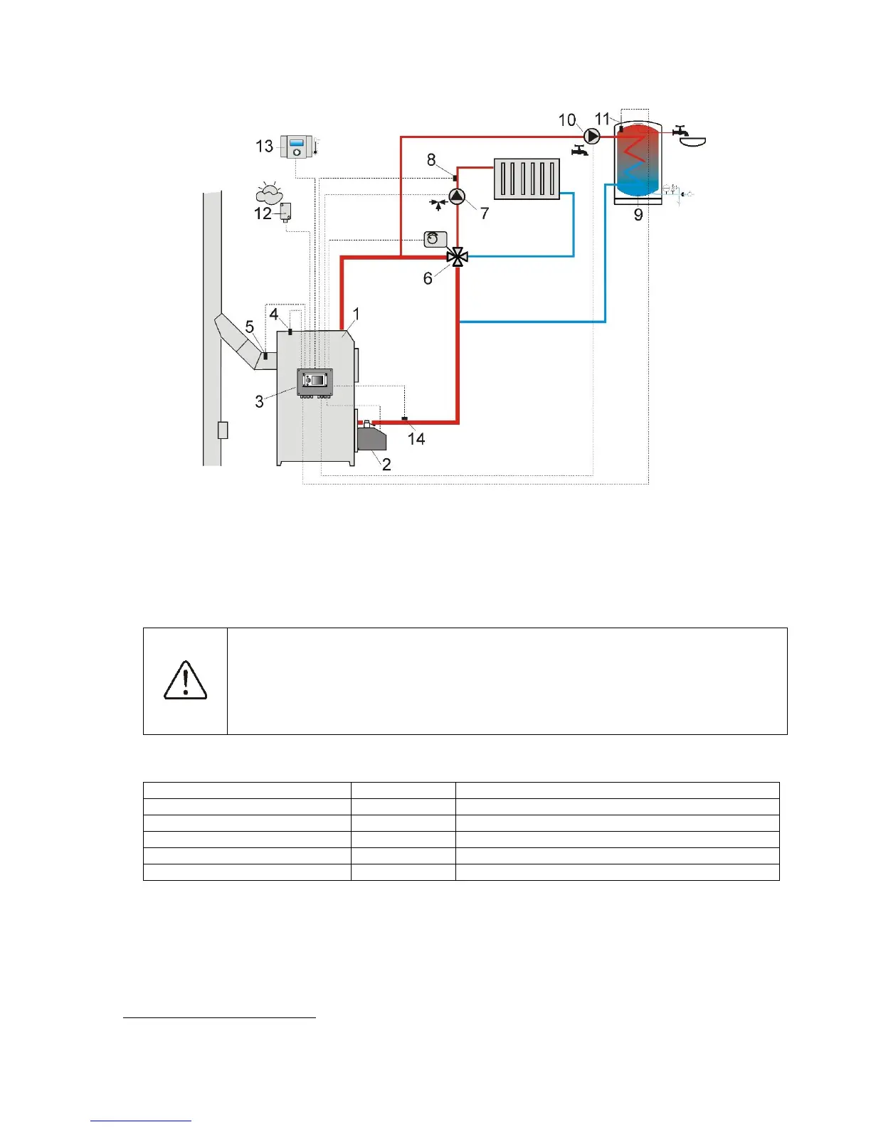
9.1 SCHEME 1
Pic. 16 Scheme with 4 way steering valve controlling central heating circuit
, where: 1 – boiler, 2 –
burner, 3 – controller, 4 – boiler temperature sensor CT4, 5 – fumes temperature sensor CT2S (only a
preview of temperature), 6 – servomotor of 4 way valve, 7 – mixer cycle pump, 8 – mixer cycle
temperature sensor, 9 –hot water container, 10 – hot water pump, 11 – hot water temp. sensor CT4, 12 –
weather temperature sensor CT4-P, 13 – room panel Room Control or standard room thermostat, 14 –
return temperature sensor CT4 (it is not necessary to operate the system).
To improve water circulation in gravity cycle it is necessary to use large nominal profiles
DN of a pipe and 4 way valve, not to use large amount of knees and profile narrowings.
Use other rules referring to gravity installations. If return sensor is installed closely, it is
necessary to isolate it thermally from surroundings and improve thermal contact with
pipe. Preset silo temperature must be set so high to ensure thermal power for mixer cycle
when at the same time heating water returning to the boiler.
Preset boiler temperature
service settings mixer settings 1
Max. Preset mixer temperature 1
service settings mixer settings 1
Shown hydraulic scheme does not replace the project of central heating and serves only as a sample!