24
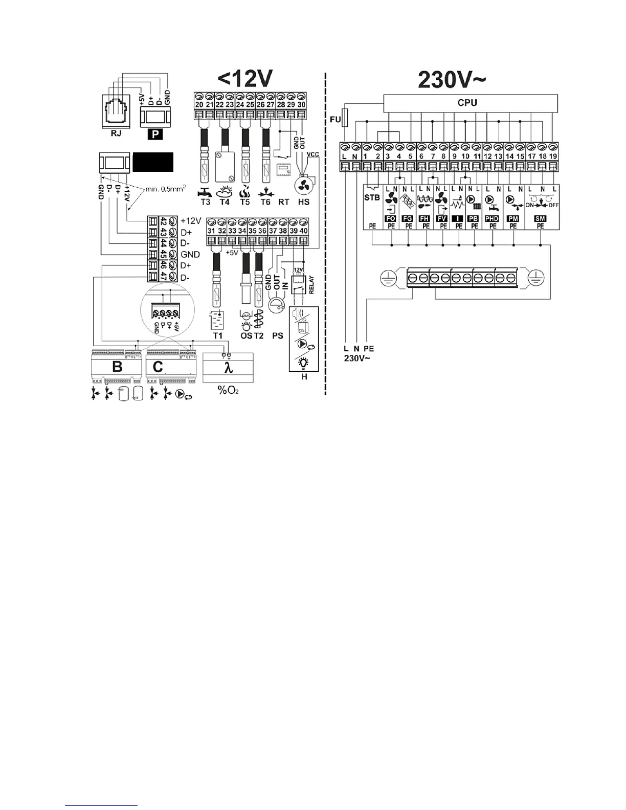
12.6 ELECTRIC SCHEME
Pic. 21 Controller wiring diagram, where: T1 – CT4 boiler temperature sensor, OS – optical flame sensor,
T2 – feeder temperature sensor CT4, PS - vacuum sensor, H – voltage output to signaling alarms or
signaling controller operation mode or control the reserve boiler or control the circulation pump, T3 - CT4
hot water temperature sensor, T4 – CT4-P weather temperature sensor, T5 – CT2S fumes temperature
sensor, T6 – CT4 mixer temperature sensor, RT – boiler room thermostat input, HS – fan revolution sensor,
P – control panel, Room Control TOUCH – room panel with a room thermostat feature (replaces RT), D-
D+ - connector for additional modules, B – module adds the control of another two mixers and a heat
buffer, C – module adding the control of another two mixers and circulating pump, λ – Lambda probe
module.
L N PE - 230V AC mains power supply, FU – mains fuse, STB – safety temperature limiter input, FO –
burner blower, FG – main feeder, FH – burner feeder or rotary grate cleaning mechanism, FV – boiler
exhaust fan, I – igniter, PB – boiler or buffer pump, PHD – hot water pump, PM – mixer pump, SM – mixer
cylinder, CPU – control.