23
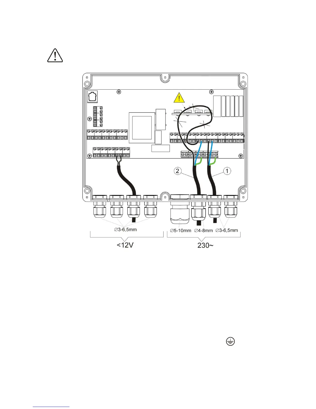
Connecting wires should not touch with surfaces with temperatures exceeding nominal
temperature of their work. Claps on the right side of the device are marked as L, N, 1-19 are
designed to connect devises powered with current 230V~.
Claps 20-40, D+, D- and RJ are designed to cooperate with low voltage devices (below 12V)..
Connecting current 230V to claps 20 – 40 and transmission connections
causes damage to the controller and brings danger of electrical shock!
Pic. 20 Wire connection, where 1 – correctly connected wire, 2 – incorrectly connected wire (it is not
acceptable to twist wires inside the device)
Wires inside the controller should be led through cable glands. Cable glands should be screwed.
Make sure that glands are correctly screwed by pulling wire. Length of isolation of external tire of
wires should be minimal, maximum 60mm. If it is necessary to longer isolate the wire tire they
should be connected with each other or other wires close to the connector. In this case when a
wire gets loose from the connector it is not in contact with dangerous parts. Isolation length of
wires entering connections are shown in the table in point 10. It is not acceptable to twist wires
and leaving unconnected wires inside the controller (risk of contact with hot parts and parts with
dangerous voltage).
12.5 SAFETY CONNECTIONS
Safety wires are to be connected with terminals marked with this symbol .