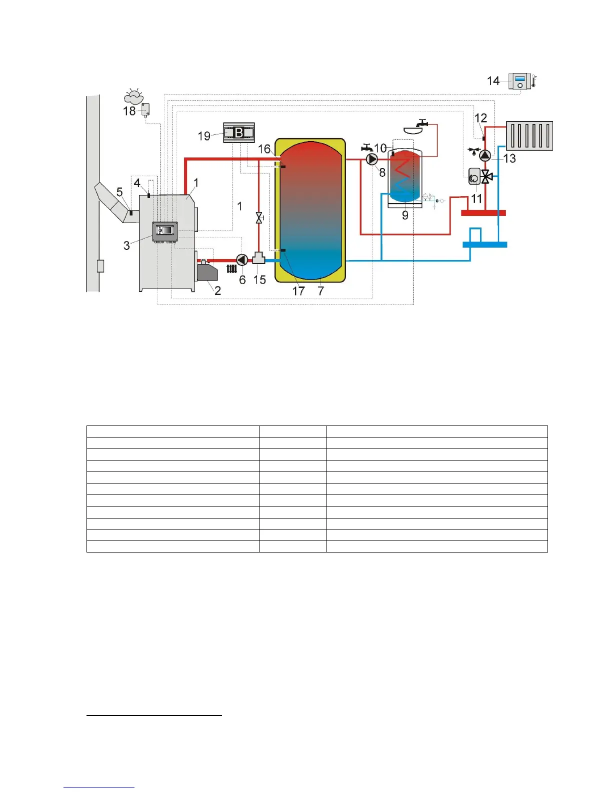
EasyManuals Logo

Pellas X S.Control User Manual

Pellas X S.Control
48 pages
To Next Page IconTo Next Page
To Previous Page IconTo Previous Page
Page #19 background imageLoading...
Page #19 background image
19
9.2 SCHEME 2
Pic. 17 Scheme with heating buffer
2
, where:1 boiler, 2 burner, 3 controller, 4 boiler temperature
sensor CT4, 5 fumes temperature sensor CT2S (only a preview of temperature), 6 boiler pump, 7
heating buffer, 8 hot water pump, 9 hot water container, 10 hot water temperature sensor CT4, 11
servomotor of mixing valve, 12 room mixer temperature sensor CT4, 13 mixer pump, 14 room panel
Room Control with room thermostat function, 15 thermostatic 3 way valve for return protection, 16
buffer higher temperature sensor CT4, 17 buffer lower temperature sensor CT4, 18 weather
temperature sensor CT4-P, 19 additional module B.
RECOMMENDED SETTINGS:
Parameter
Setting
MENU
Preset boiler temperature
80C
boiler settings
CH pump activating temperature
55C
service settings CH and HUW settings
Activating operation (buffer service)
activated
service settings buffer settings
Buffer loading start temperature
50
service settings buffer settings
Buffer loading stop temperature
75
service settings buffer settings
Mixer service 1
activated CO
service settingsmixer settings 1
Max mixer preset temperature 1
70
service settingsmixer settings 1
Mixer heating curve 1
0.8 1.4
mixer settings 1
Mixer weather control 1
activated
mixer settings 1
Mixer thermostat selection 1
ecoSTER T1
service settings mixer settings 1
2
Shown hydraulic scheme does not replace the project of central heating and serves only as a sample!

Table of Contents

Questions and Answers:

Question and Answer IconNeed help?

Do you have a question about the Pellas X S.Control and is the answer not in the manual?

Pellas X S.Control Specifications

General IconGeneral
BrandPellas X
ModelS.Control
CategoryController
LanguageEnglish