6 Prima 451 – User Manual
3. Description
3.1 General C
on
s
t
r
u
c
t
i
on
F
r
a
m
e
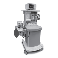
The machine has a cast aluminium base, extruded aluminium
uprights, with aluminium and plastic mouldings.
M
ob
ili
t
y
Four castors are fitted, with a brake on each. The castors are
125 mm diameter. Always apply the brakes in the MRI facility
A footrest is built into the front of the machine and, to aid
manoeuvrability, a handle is provided at the front of the
machine.
Mounting
posts and
b
r
a
ck
e
t
s
A mounting system is built into each pair of side uprights,
to allow the use of pole-mount brackets, V-brackets, and
ventilator mounting brackets.
The pole mount upright is used to mount an A200SP
Absorber assembly.
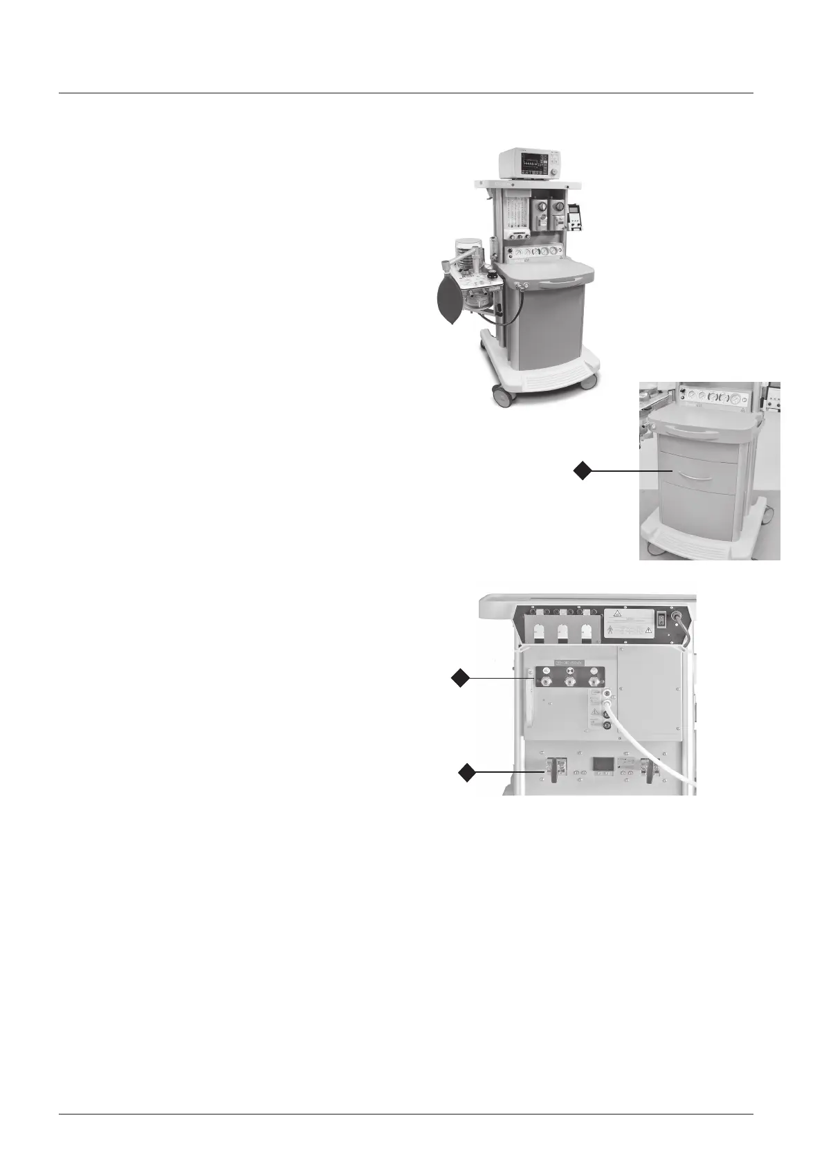
Drawer unit (optional)
W
A
RN
I
N
G
As part of the pre-use check procedure, empty the drawer
(1) and check each item.
Remove anything metallic, or with metallic content, from
the MRI scanning room.
3.2 Gas C
i
r
c
u
i
t
Gas
Circuit
S
c
h
e
m
a
t
i
c
A gas circuit schematic is shown on the following page.
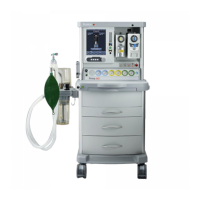
Cylinder
Y
o
k
e
s (1)
W
A
RN
I
N
G
Use only non-magnetic cylinders with this machine. Steel
cylinders can cause serious injury or death if brought into
an MRI scanning room.
The yokes are rear mounted and conform with ISO standards
for pin-index fitting.
To ensure that only cylinders of the appropriate gas may be
installed the yokes are designed so that the retaining latch
cannot be closed unless the index pins are fully engaged.
Pipeline Inlets (2)
Up to three, rear mounted pipeline gas inlets can be fitted.
Pipeline supply hoses are connected by territory-specific,
non-interchangeable, screw threaded unions (section 4.2).
C
A
U
TIO
N
A malfunction of the central gas supply within your facility
may cause immediate cessation of gas delivery and total
anaesthesia system failure.
F
il
t
e
r
s
To prevent dirt entering the gas system, a filter is fitted to
each cylinder yoke and pipeline inlet.
Gas Inlet
Block
Each individual cylinder, or pipeline supply, is routed through
a separate gas block.
Each gas block has an integral high pressure gauge tapping
for direct mounting of a pressure gauge, and a non-return
valve to prevent back flow of gas.
In addition, cylinder gas blocks have:
(a) A diaphragm pressure regulator to reduce the pressure of
the compressed gas supply, and
(b) A pressure relief valve, factory set to 517 kPa (75 psi). This
prevents pressure build up under the diaphragm should any
leakage develop across the reducing valve seat.
2
1
1