24 Prima 451 – User Manual
2
3
Installation and Pre-use Checks
5.4
Electrical
Supply
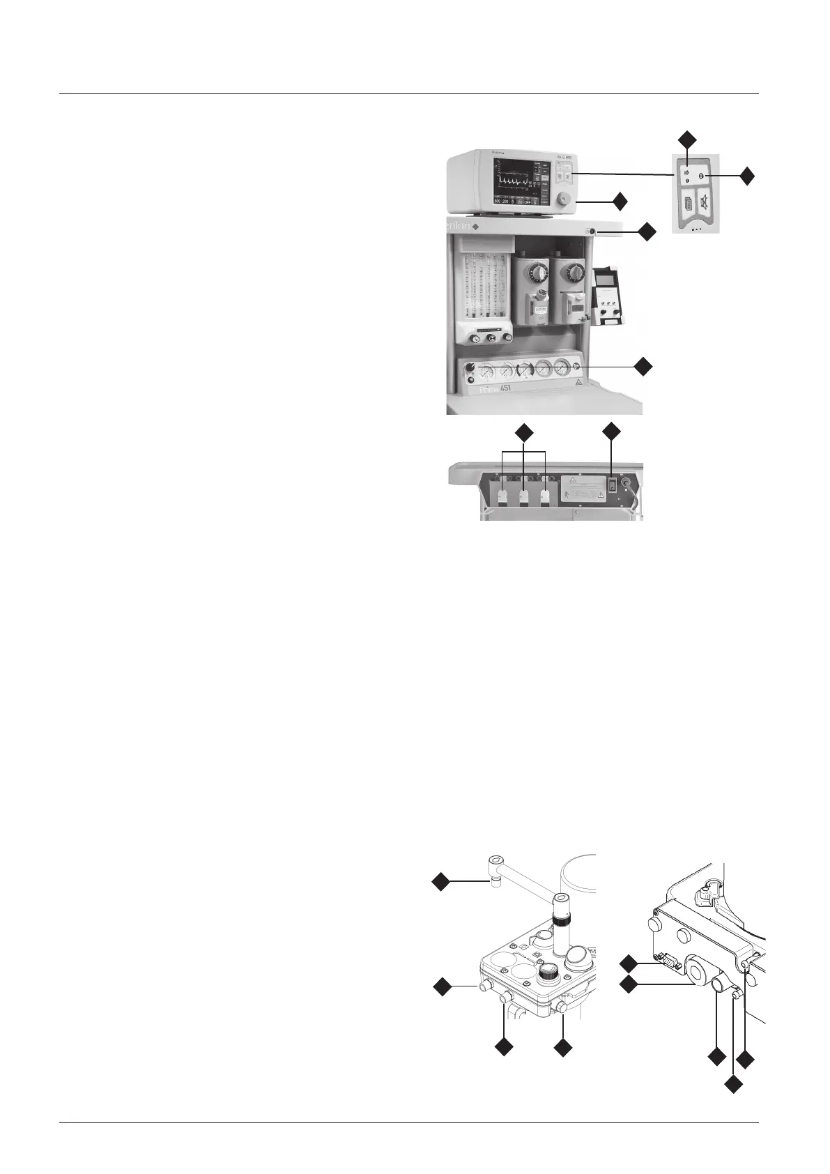
1. Connect the machine power lead to a suitable mains supply
socket. Check that the mains indicator light (1) is on.
2. Set the auxiliary power supply switch (2) to ON.
Check for correct function of each auxiliary power outlet (3)
3. Check all electrical equipment, including devices powered by
the power outlets on the rear of the machine.
4. AV-S Ventilator (4).
Check the power supply to the ventilator:
a) Turn the Prma 451 gas delvery swtch (5) to On
Press the ventlator on/off swtch (6)
heck that the green ndcator lght (7) s llumnated
Note that the gas delivery switch (5) must be in the ‘On’
position.
5.5 Patient
Breathing
S
ys
t
e
m
5.5.1 Hose C
onn
e
c
t
i
on
s
Check that all hoses are secure.
5.5.2
Breathing
System Hose, Re
s
e
r
v
o
i
r
Bag,
V
e
n
t
il
a
t
o
r
Connectors for the Inspiratory hose and expiratory hose, and the
reservoir bag connector are 22 mm male. All connectors comply
with ISO 5356/1. Check all connections for gas tightness.
5.5.3 Fresh Gas
S
upp
l
y
The fresh gas hose assembly supplied with the machine has a
Penlon connector at the absorber inlet and a 22 mm taper at
the other end for connection to the common gas outlet of the
anaesthetic machine. Check all connections for gas tightness.
5.5.4 A200SP MRI
Absorber
WARNING
Do not use the system in the MR facility if the absorber has a
heater fitted.
Always
follow
the pre-use check
procedures
in the user
manual
supplied
with
t
h
e a
b
s
o
r
b
e
r
. Use an oxygen monitor (and a CO
2
analyser) when using any rebreathing anaesthetic system.
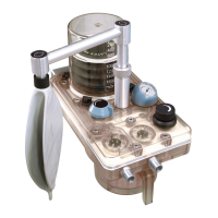
A200SP MRI C
onn
e
c
t
i
on
s
1. Inspiratory Connector
2. Expiratory Connector
3. Bag connector
4. Inlet - from DRIVE GAS outlet on ventilator control unit.
5. Inlet - fresh gas hose from Common Gas Outlet
6. Exhaust outlet from APL Valve - connect to Anaesthetic Gas
Scavenge System
7. Oxygen monitor sensor
8. Outlet - sample line to ventilator Pressure Monitor port.
9. Interface cable - Bag/Vent switch and spirometer (connects
internally to the AV-S MRI
ventilator).
3
2
1
7
6
9
8
4
5
7
1
5
4
6