Prima 451 – User Manual 25
Installation and Pre-use Checks
5.5.5 System Low Pressure Leak
T
e
s
t
Connect the CGO outlet on the machine to the fresh gas inlet
of the A200SP MRI absorber
NOTE
This machine must be fitted with a breathing system
complying with approved design parameters, at the
selection of the qualified practitioner.
The breathing system components do not constitute part
of the machine but connections between the machine and
breathing system should be verified as follows:
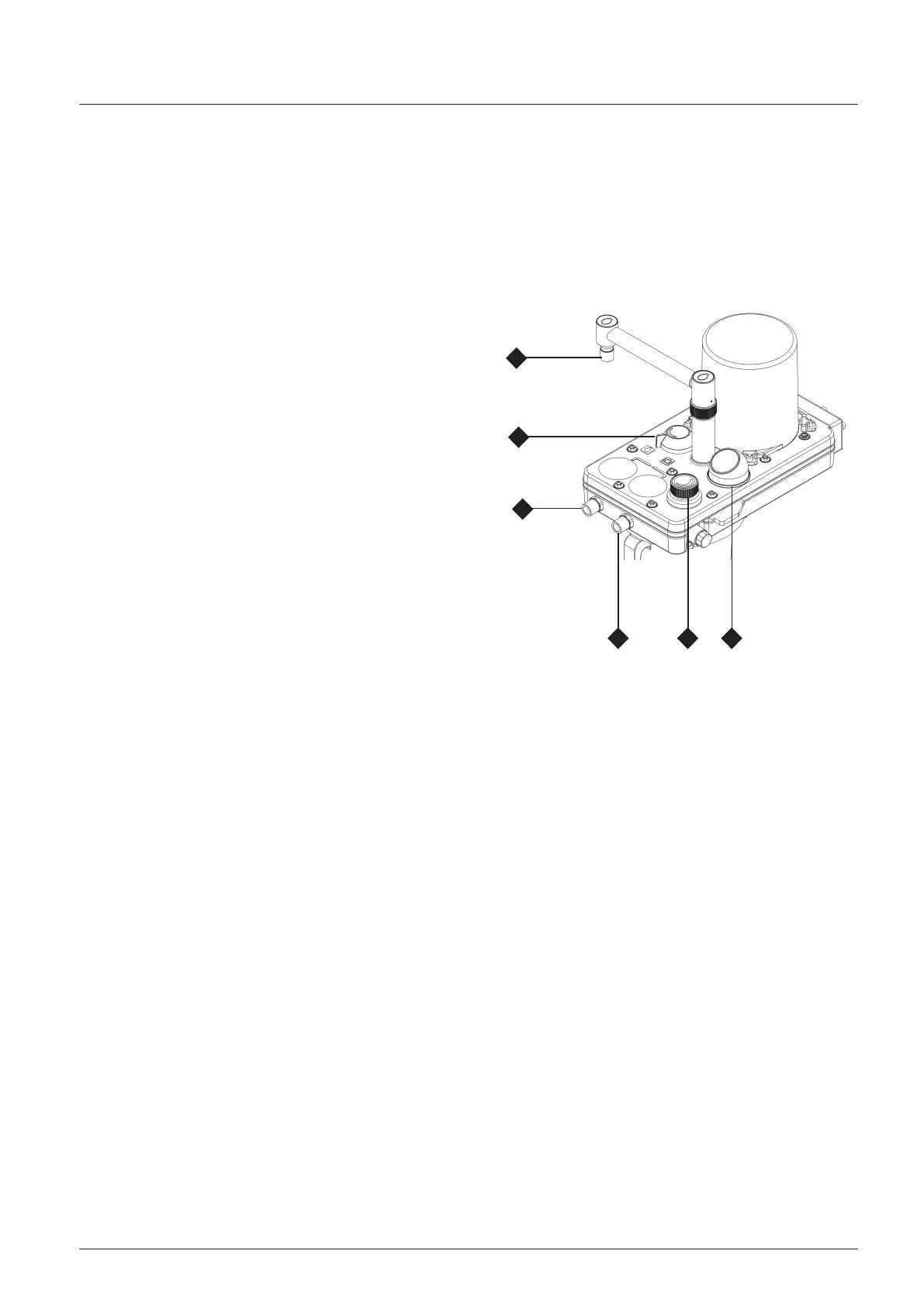
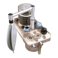
1. Fit a patient circuit to the inspiratory connector (1) and
expiratory connector (2) on the absorber, and a breathing
bag to the bag arm connector (3).
2. Set the bag/ventilator switch (4) on the absorber to ‘Bag’
3. Close the adjustable pressure limiting (APL) valve (5), and
occlude the patient connection port on the patient circuit.
Press the oxygen flush valve button on the front of the
machine briefly.
Check that the reservoir bag inflates and the manometer
(6) indicates approximately 40 cmH2O.
4. Release the oxygen flush valve.
Check that the pressure is maintained in the system
with less than 200 ml/min fresh gas delivered into the
breathing system, showing that no leaks are present.
5. If this test fails, recheck the low pressure system on the
machine (section 5.2.4).
If the low pressure test on the machine is successful,
check the ventilator and absorber, referring to the
relevant user instruction manual.
5.5.6
Breathing Circuit
S
c
h
e
m
a
t
i
c: AV-S MRI
Ventilator
Heat and moisture exchanger
NOTE
To protect the expiratory limb of the breathing circuit, and
the spirometer, use a breathing circuit bacterial filter (see
schematic on following page, item 4), and a heat and moisture
exchanger (see schematic, item 6) at the patient Y-piece.
C
A
U
TIO
N
Replacement/Disposal - always follow the instructions
supplied with the filter or heat and moisture exchanger.
Always renew components at the recommended interval.
Connection to analysers and monitors
Follow the instructions in the relevant user manual for
connection to analysers and monitors.
Interface cabling is shown for Prima 451 On/Off switch and
A200SP Bag/Vent switch and spirometer.
Ventilator connections shown are for AV-S MRI ventilator with
spirometry and oxygen monitor.
For A200SP MRI and Nuffield 200 MRI ventilator, refer also
to the user manuals supplied with those products.
3
4
2
1 5 6