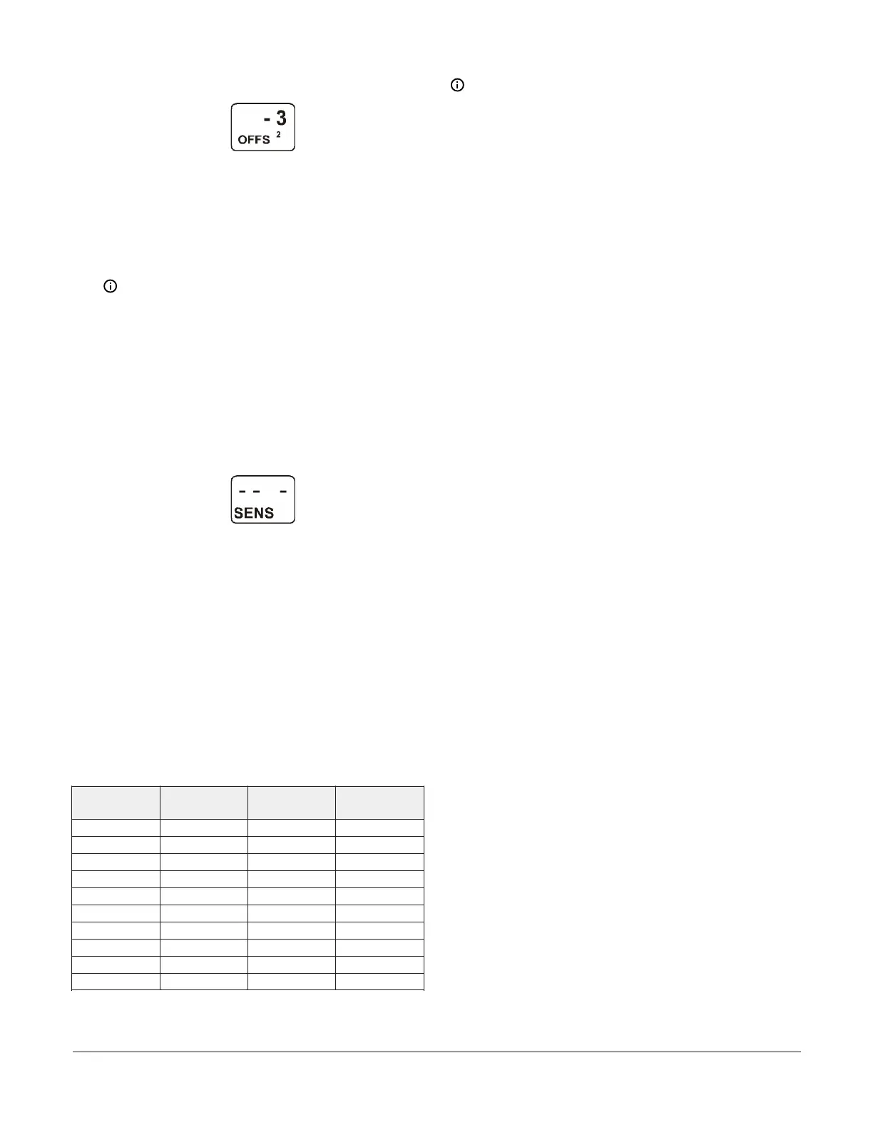
Figure 14: Temperature Offset Selection screen
6. After you set up the sensors for your control system:
- Press M to scroll through the Output Setup
Start screens and begin setting up your
system outputs.
- Press Up and Down simultaneously to return
to the Main screens.
Note: When you finish setting up all of the
sensors for your control system, the display
returns to the Sensor Setup Start screen. You
can edit the sensor setup values at any time, if
required. However, changing the Sensor Type
for a sensor that is referenced by an output
requires setting up the output again to the new
Sensor Type values.
The following figure shows the Sensor Setup
Start screen with flashing dashes.
Figure 15: Sensor Setup Start screen
Setting up Outputs that reference a P 110
Sensor
The P 110 Sensor Type can monitor negative pressure
down to 20 InHg (-10 psi). When referencing a P 110
sensor, System 450 displays negative pressure values in
InHg on the Main and System Status screens.
But when you set up an output that references a P 110
sensor and the setup value is a negative pressure value,
you must select a pressure value in negative psi.
Use Table 4 to determine the negative PSI setup value
that corresponds to your InHg target value. For example,
if you want a relay output to go off when the sensed
pressure reaches 7 InHg, you select the value -3.5 (psi) in
the output’s Relay OFF Selection screen.
Table 4: InHg target values and PSI setup values
InHg value psi setup
value
InHg value psi setup
value
1 -0.5 11 -5.5
2 -1.0 12 -6.0
3 -1.5 13 -6.5
4 -2.0 14 -7.0
5 -2.5 15 -7.5
6 -3.0 16 -8.0
7 -3.5 17 -8.5
8 -4.0 18 -9.0
9 -4.5 19 -9.5
10 -5.0 20 -10.0
Note: When an output references the P 110 Sensor
Type and the output is set up for Differential Control
(Sn-1 and Sn-2 are P 110 Sensor Type), the negative
pressure values displayed in the differential pressure
System Status screen (dIFP) appear as negative psi
values, not InHg values. See Differential control for
more information.
Binary Input control for Relay Outputs
You can connect a binary input (dry contacts) to any of the
three System 450 communications control module inputs
(Sn1, Sn2, or Sn3), and control the output relays in your
control system based on the binary input’s state (open or
closed).
A sensor (Sn-1, Sn-2, or Sn-3) set up as a binary input can
only be referenced by a relay output. Sensors set up as
binary inputs are not available for selection on analog
outputs.
When a relay output references a sensor that is set up
as a binary input, the On and OFF parameter screens
are not available as you set up the output. The relay
output’s On/Off state is controlled by the binary input’s
Closed/Open state and any of the timer parameters (ONT,
OFFT, ONd, or OFFd) that you set up for the relay output.
Refer to the Binary Input Control for Relay Outputs
section of the System 450 Series Modular Control Systems
with Communications Control Modules Technical Bulletin
(LIT-12011826) for more information.
High Input-Signal selection
System 450 control modules with communications include
the High Input-Signal selection control feature.
The High Input-Signal selection feature enables a System
450 control system to monitor a condition (temperature,
pressure, or humidity) with two or three sensors (of the
same type) and control relay and/or analog outputs based
on the highest condition value sensed by the two or three
referenced sensors.
In two sensor applications (HI-2), Sn-1 and Sn-2 must be
the same Sensor Type. In three sensor applications (HI-3),
Sn-1, Sn-2, and Sn-3 must be the same Sensor Type.
A System 450 control system, using High Input-Signal
selection, can monitor the outlet pressures of two
condenser coils in a multi-circuit condensing unit using
two pressure sensors of the same type; one connected to
each coil outlet.
Differential control
System 450 control modules with communications include
the Differential Control feature. Differential control is used
to monitor and maintain a given difference in a condition
(temperature, pressure, or humidity) between two sensor
points within a system, process, or space.
The Differential Control feature enables a System 450
control system to monitor the temperature, pressure, or
humidity differential between two sensors of the same
type (Sn-1 and Sn-2) and control relay and/or analog
outputs based on the sensed differential value relative
to user-selected differential values (dON, dOFF, dSP, and
dEP).
System 450 Series Control Module with Ethernet Communications Installation Guide10
 Loading...

