Table 9: System 450 web UI Sensor Configuration page user actions, descriptions, and references
Callout Identifier User actions, descriptions, references
18 Cancel button Click Cancel to cancel any changes you made on this web page, revert to the previous values
on the web page, and go to the System Configuration page.
1 Whenever Sn-1 and Sn-2 are set up with the same sensor type, the Sn-d (Differential Sensor) 1 automatically set up and made
available in the SENS drop-down menus in the Output Configuration pages. You are not required to use Sn-d, but the Sn-d status
is displayed in the System Overview page, Sensor Configuration page, System Configuration page, and the Output Configuration
pages.
Analog Output Configuration page
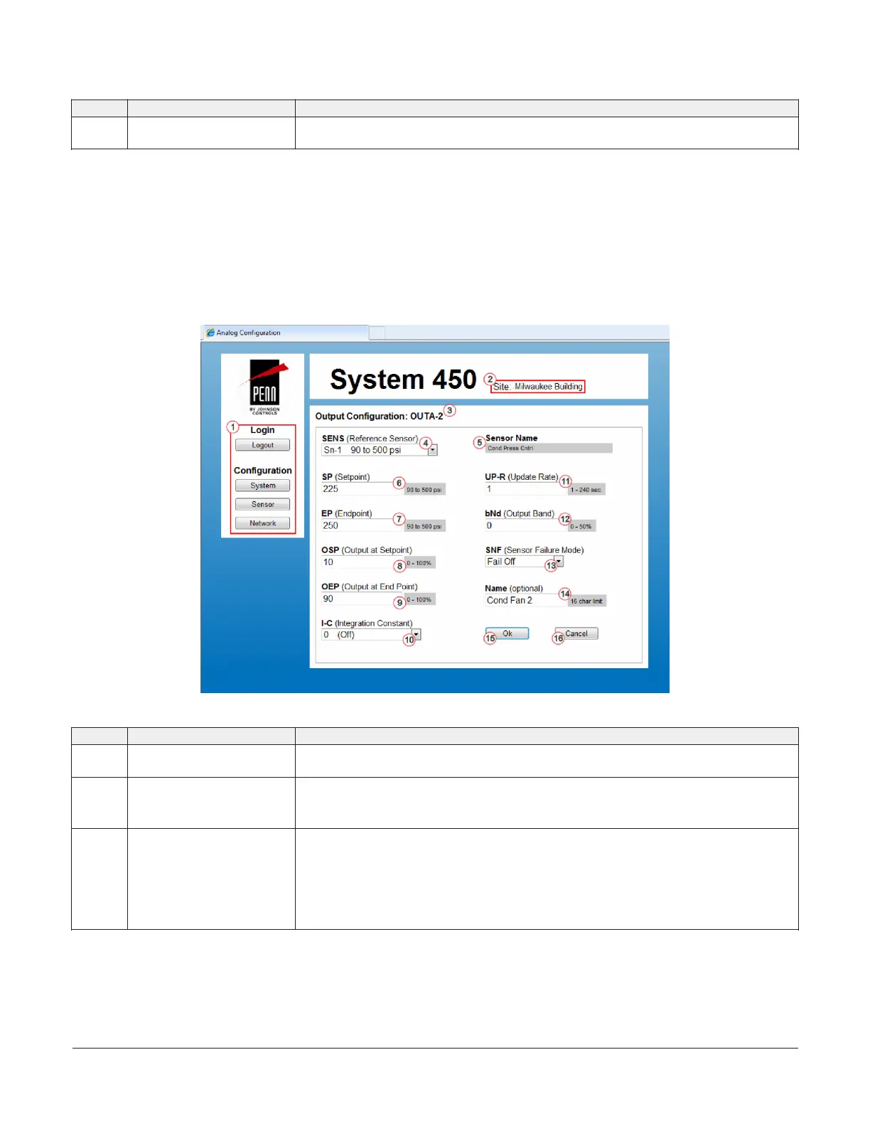
Figure 66 shows an example Analog Output Configuration Page for a System 450 control system that is set up and
operating. Table 10 provides descriptions, user actions, and references for the items called out in Figure 66.
Figure 66: System 450 Analog Output Configuration page example
Table 10: System 450 web UI Analog Output Configuration page user actions, descriptions, and references
Callout Identifier item name User actions, descriptions, references
1 Logout and Configuration
buttons
See System Configuration page for descriptions and user actions regarding the System,
Sensor, and Network buttons.
2 Site name Displays the assigned site name. You can assign a website name on the Network
Configuration page.
See Network Configuration page for more information about assigning a site name.
3 Output configuration: OUTA-2 Displays the output type (OUTA or OUTR) and output number (-n), which are assigned by the
control module.
When you first power on a System 450 module assembly, the control module automatically
detects the connected outputs and assigns an output type and number for each connected
output.
In this example, an analog output is detected and identified in the number 2 position in the
module assembly (OUTA-2).
System 450 Series Control Module with Ethernet Communications Installation Guide 31
 Loading...

