Network Configuration page
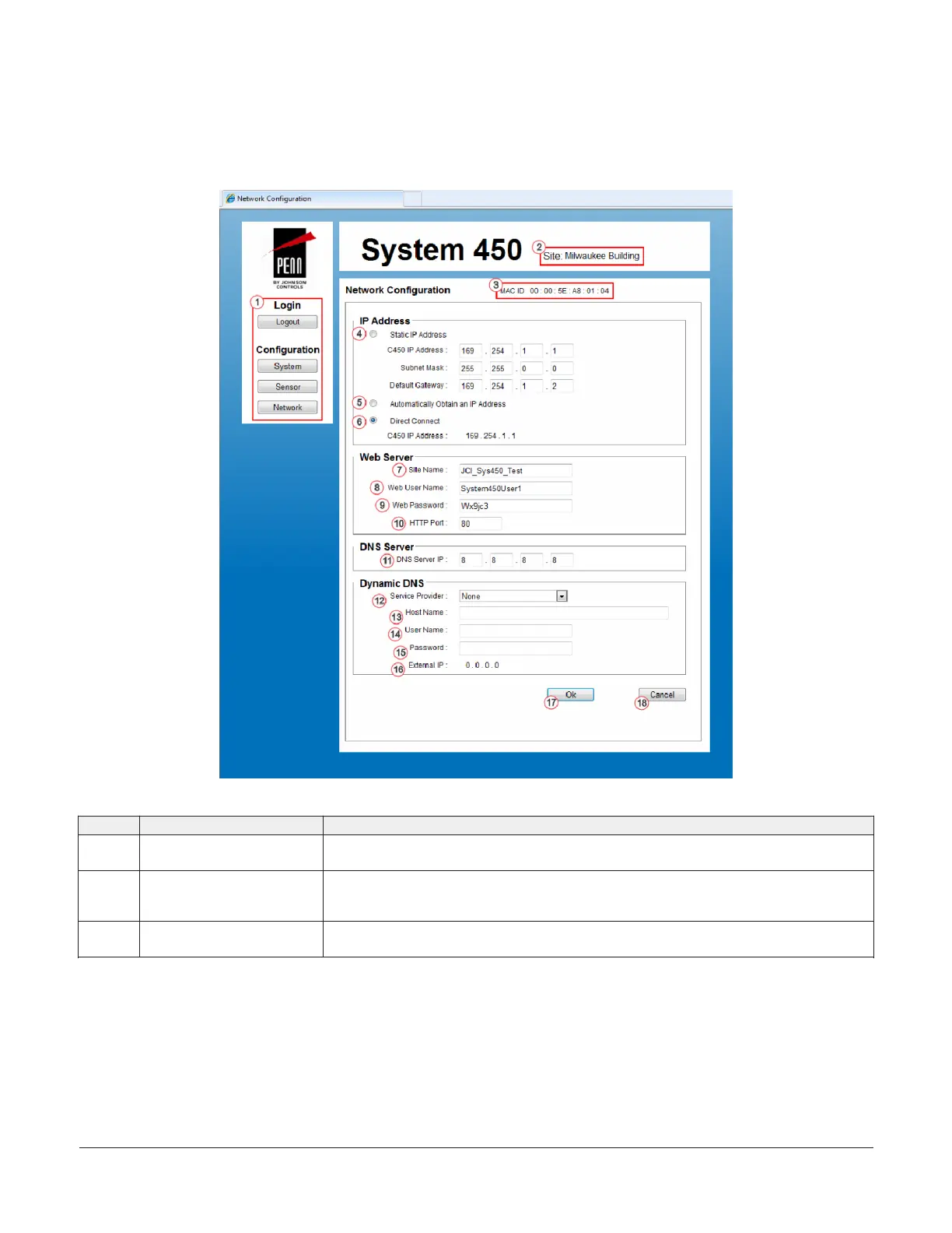
Figure 68 shows an example Network Configuration Page for a System 450 control system that is set up and operating.
Table 12 provides descriptions, user actions, and references for the items called out in Figure 68.
Figure 68: System 450 Network Configuration page example
Table 12: System 450 web UI Relay Output Configuration page user actions, descriptions, and references
Callout Identifier item name User actions, descriptions, references
1 Logout and Configuration
buttons
See System Configuration page for descriptions and user actions regarding the Logout,
System, Sensor, and Network buttons.
2 Site name Displays the assigned site name. You can assign a website name on the Network
Configuration page.
See Site Name below for more information about assigning the site name.
3 MAC ID Displays the unique physical address assigned to the communications control module when
the module is manufactured. A module’s MAC ID address cannot be changed.
System 450 Series Control Module with Ethernet Communications Installation Guide 35
 Loading...

