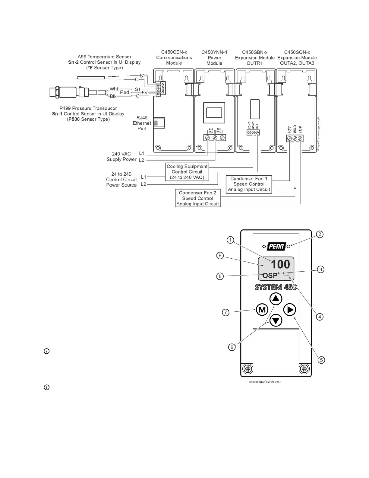
Figure 3: Example System 450 Control System with an Ethernet Communications Module controlling a cooling
system with condenser fan speed control
Setup and adjustments
A System 450 control system consists of one control
module, one to three control sensor inputs, and one to
ten outputs that provide on/off control or analog control.
Figure 3 shows an example System 450 control system
module assembly, with two sensors and three outputs,
connected to an Ethernet network.
Building a System 450 Module assembly
1. Determine the controlled conditions, sensor types,
and value ranges required for your application, and
select the appropriate System 450 sensor types.
2. Determine the number and type (relay or analog)
of outputs required to control your application, and
select the appropriate System 450 control module
and expansion modules to provide the outputs.
3. Assemble the control and expansion modules in the
proper order, starting with the control module on
the left.
Note: If you use a C450YNN-1C power module,
it must be plugged into the control module.
Plug in any expansion modules to the right of
the power module.
4. Apply supply power to the module assembly.
Note: After you power on your module
assembly, you can set up your control system
in the control module UI before wiring the
sensors or outputs to your assembly.
Figure 4: System 450 Communications Module LEDs, LCD,
four-button touchpad UI
System 450 Series Control Module with Ethernet Communications Installation Guide4
 Loading...

