• Do not connect 24 VAC supply power to the
System 450 modules before finishing wiring and
checking all wiring connections. Short circuits or
improperly connected wires can result in damage
to the modules and void any warranty.
• A System 450 control module and module
assembly can be connected to an internal power
source (a System 450 power module) or an
external power source (24 V power connected
to the 24V and COM terminals on the control
module), but must not be connected to both
power sources simultaneously. Connecting a
control module to both internal and external
power sources can damage the modules and void
any warranty.
• When connecting System 450 compatible sensors
with shielded cable to a System 450 control
module, connect the cable shield drain lead to one
of the C (common) terminals on the input sensor
terminal block. Do not connect the shield at any
other point along the cable. Isolate and insulate
the shield drain at the sensor end of the cable.
Connecting a cable shield at more than one point
can enable transient currents to flow through
the sensor cable shield, which can cause erratic
control operation.
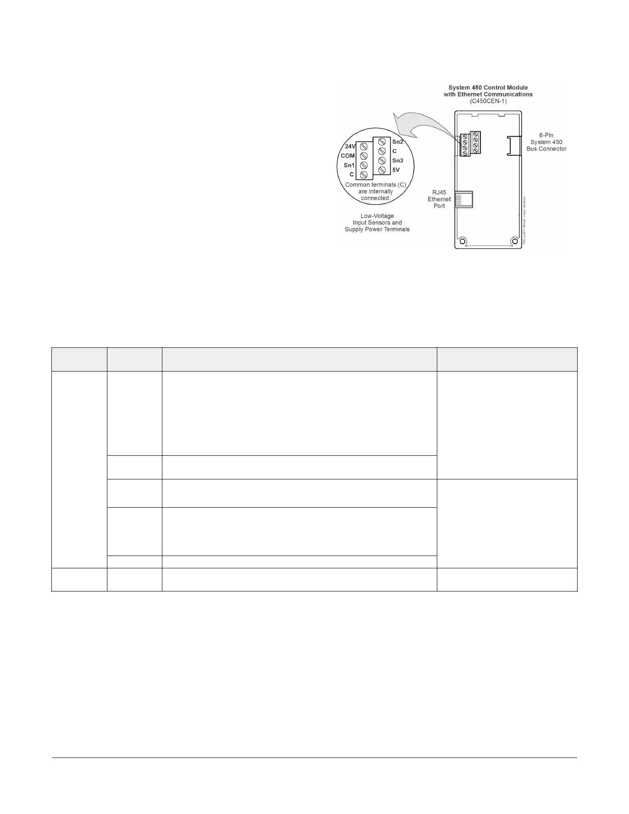
Figure 2: C450CEN-x Control Module with Ethernet
communications showing wiring terminals
Table 1: System 450 Control Module with Ethernet communications wiring information
Terminal
block
Label Function, electrical ratings, and requirements Recommended cable type and
wire sizes
24V Provides internal 24 VAC power at terminals for (humidity) sensors
when a C450YNN power module is connected in the control system
module assembly.
or
Accepts external 24 VAC (20–30 VAC) supply power for the control
system when a C450YNN power module is not connected in the
control system module assembly.
COM Provides the common connection for 24 VAC power terminal for either
internally or externally supplied 24 VAC power (only).
0.08 mm
2
to 1.5 mm
2
28 AWG to 16 AWG
S1, S2, S3
1
Accepts passive or active (0–5 VDC) input signals from control
sensors.
1
C, C Provide low-voltage common connections for the sensors connected
to the 5V, Sn1, Sn2, or Sn3 terminals (only).
The two C terminals are used for sensor common connections only.
The two C terminals are connected internally.
Low-voltage
and Input
Sensors
terminal
block
5V Provides 5 VDC power for active sensors.
0.08 mm
2
to 1.5 mm
2
28 AWG to 16 AWG
Ethernet port Provides 8-Pin RJ45 modular jack for connecting to an Ethernet
network.
CAT 5 straight-through or crossover
cable
1 For sensor wire runs greater than 50 ft (15.2 m) or where the sensor wiring is exposed to electromagnetic or radio frequency
interference, use shielded cable and connect the shield to a C (common) terminal on the control module.
System 450 Series Control Module with Ethernet Communications Installation Guide 3
 Loading...

