To change the sensor the output references,
press Up or Down in the Edit Sensor Selection
screen to select the new sensor that the out-
put references. Then press Next to save the
new sensor selection and return to the Setpoint
Selection screen (SP or dSP). If the new sensor
has a different Sensor Type from the previously
referenced sensor, repeat the output setup pro-
cedure for the output.
Note: If you change the sensor that an output
references to a sensor with a different Sensor
Type, the default setup values for the output
change, and you must set up the output again.
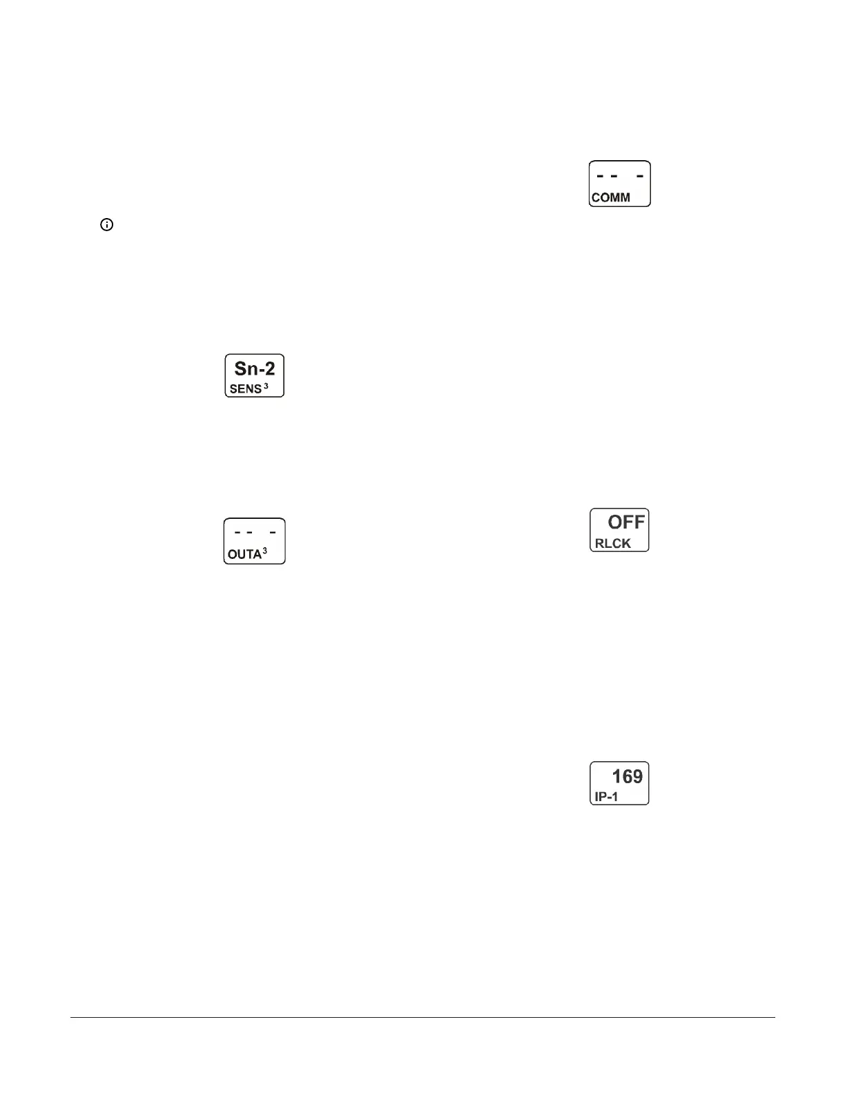
The following figure shows Sn-2 as the selected
Sensor for Output 3.
Figure 42: Edit Sensor Selection screen
12. After you set up the analog output, press Up to scroll
through the remaining Output Setup Start screens
and return to the Sensor Setup Start screen, or press
Down and Next simultaneously to return to the
System 450 Main screens. The following figure shows
the Analog Output Setup Start screen for Output 3.
Figure 43: Analog Output Setup Start screen
Viewing network settings, setting the remote
network UI access lock, and resetting the
network settings
In the Communications View and Setup Start screens,
you can set up the Ethernet communications parameters
for the System 450 control module. You must use a web
browser on a computer that is connected to the control
module.
Refer to the System 450 Series Modular Control Systems
with Communications Control Modules Technical Bulletin
(LIT-12011826) for more information and procedures for
setting up a System 450 control module with Ethernet
communications.
This section provides procedures, screen examples, and
general information for setting up a System 450 control
module with communications on an Ethernet network.
You can use an Ethernet patch cable to connect your
computer or laptop directly to the System 450 control
module with Ethernet communications.
The default (factory set) Ethernet IP address for a System
450 control module with Ethernet communications is
169.254.1.1.
1. In the Communications Setup Start screen, press
Next to go to the Remote Network Access Lock
screen.
Figure 44: Communications Setup Start screen
2. In the Remote Network Access Lock screen, select
On or OFF and press Next to save the selection and
go to the next screen.
You can lock or unlock remote access (with Eth-
ernet) to the System, Sensor, and Network web
pages in the control module’s web UI. When On
is selected, the login fields on the Home page
are not available; remote users can access only
the System 450 Home page and view the sys-
tem status. Select OFF to enable the login fields,
which allow web users to log into the UI and
access the setup screens.
The following figure shows the Remote Network
Access Lock is set to OFF, indicating that remote
access is permitted. Remote Access refers to
the ability to make configuration changes to the
device through the Ethernet connection.
Figure 45: Remote Network Access Lock screen
3. In the First IP-Address Octet Display screen, press
Next to go to the next screen. The First IP-Address
Octet Display screen shows the first octet (one to
three numerals) of the control module IP address.
This is a view-only screen. The control module’s IP
address is set up using a client computer connected
to the control module.
The following figure shows the first IP address
octet value 169 for the complete example IP
address of 169.254.1.1, which is the factory-
default IP address.
Figure 46: First IP-Address Octet Display screen
4. In the Second IP-Address Octet Display screen,
press Next to go to the next screen. The Second
IP-Address Octet Display screen shows the second
octet (one to three numerals) of the control module
IP address. This is a view-only screen. The control
module’s IP address is set up using a client computer
connected to the control module.
The following figure shows the second IP
address octet value 254 for the complete exam-
ple IP address of 169.254.1.1, which is the
factory-default IP address.
System 450 Series Control Module with Ethernet Communications Installation Guide 19
 Loading...

