Figure 47: Second IP-Address Octet Display screen
5. In the Third IP-Address Octet Display screen, press
Next to go to the next screen. The Third IP-Address
Octet Display screen shows the third octet (one to
three numerals) of the control module IP address.
This is a view-only screen. The control module’s IP
address is set up using a client computer connected
to the control module.
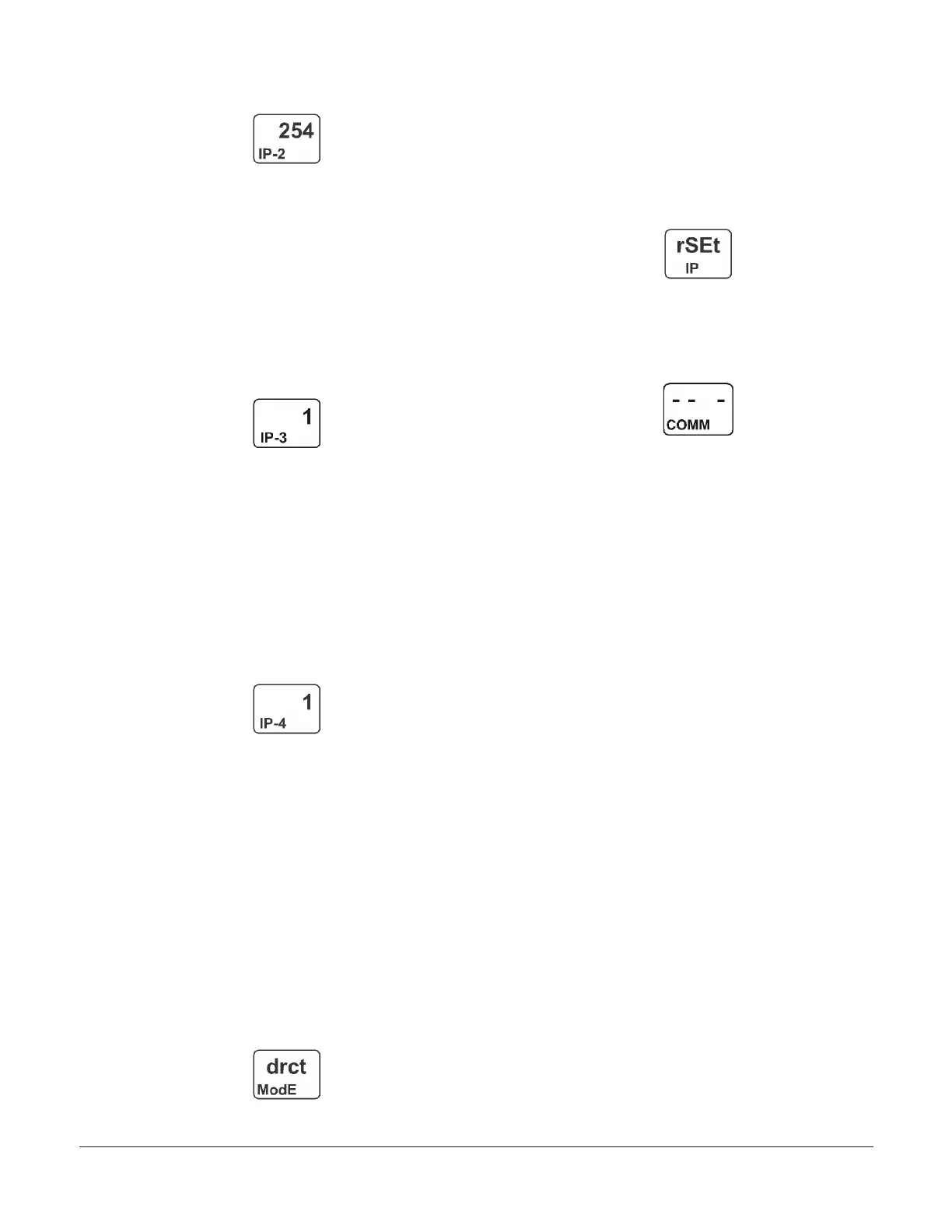
The following figure shows the third IP address
octet value 1 for the complete example IP
address of 169.254.1.1, which is the factory-
default IP address.
Figure 48: Third IP-Address Octet Display screen
6. In the Fourth IP-Address Octet Display screen,
press Next to go to the next screen. The Fourth
IP-Address Octet Display screen shows the fourth
octet (one to three numerals) of the control module
IP address. This is a view-only screen. The control
module’s IP address is set up using a client computer
connected to the control module.
The following figure shows the fourth IP
address octet value 1 for the complete example
IP address of 169.254.1.1, which is the factory-
default IP address.
Figure 49: Fourth IP-Address Octet Display screen
7. After you configure the network parameters for your
control module in the web UI and reset the control
to implement your network settings, press Next to
go to the next screen. The Network Address Mode
Status screen displays the Network Address mode
that control module is configured to operate in. This
is a view-only screen. The three available modes are:
- drct ModE (Direct Connection mode)
- StAt ModE (Static IP Connection mode)
- Auto ModE (Automatically Obtain IP Address
mode)
This following figure shows that the communi-
cations control module is in the Direct Connec-
tion mode.
Figure 50: Network Address Mode Status screen
8. While rSEt is blinking, press and hold Down for 5
seconds to restore the control module’s network
configuration values to the original default values,
and place the communications control module in the
Direct Connection mode. When rSEt stops blinking,
the reset is complete. Press Next to go to the next
screen.
Figure 51: Reset Default Network Configuration screen
9. Press Next to go to the Remote Network Access
Lock screen, or press M to scroll through the System
Setup Start screens, or press and hold Down and Up
simultaneously to return to the Main screens.
Figure 52: Communications Setup Start screen
Setting up password protection
System 450 communications control modules provide
password-protected access to your System 450 control
systems. You can operate your control system with or
without password protection.
There are two password types for accessing the local
(touchpad) System 450 UI—a User level password and
an Administrator (Admin) level password. Both local UI
passwords are four-digit values (0000 to 9999).
The User password allows you to access the System Setup
screens from the System Status screens.
When the User password is set to the factory-default
value of 0000, password-protected access is disabled,
and a password is not required to access the System
Setup screens and change control system parameters and
values. Changing the User password to a value other than
0000 enables password-protected access.
The Admin password allows you access to the System
Setup screens just like the User password. The Admin
password also provides access to the User Password
Setup screens and the Administrator Password Setup
screens, and change the password values. The factory-
default Admin password is 1234.
The User and Admin Password Setup screens behave
differently than the other System Setup screens. In the
System Setup screens, the entire parameter value blinks
and you enter an entire new value, then press Next to
save the entire value and go to the next screen.
In the User and Admin Password Setup screens, you must
enter each digit in a screen individually and press Next to
save the single-digit value and go to the next digit in the
four-digit password string.
When you press Next to save the last digit in the Change
User Password or Change Admin Password screens, the
password is saved and the UI displays the next screen.
When you press Next to save the last digit in the Confirm
Admin Password screen, the password is confirmed and
the UI displays the Validate Admin Password Change
screen.
System 450 Series Control Module with Ethernet Communications Installation Guide20
 Loading...

