When a Differential Control sensor (Sn-d) is set up, the
displayed differential sensor value is a calculated variable
value: (Sn-d) = (Sn-1) – (Sn-2).
The Sn-d value appears in the System Status screens as
either a temperature differential value (dIFT), pressure
differential value (dIFP), or humidity differential value
(dIFH). The unit of measurement associated with the
displayed differential value is determined by the Sn-1 and
Sn-2 Sensor Type. See Table 3 for Sensor Types and their
units of measurement.
The relay output setup values dON and dOFF are
condition differential values. When a relay output is set
up for differential control, System 450 controls the relay
state (On or Off) based on the difference between Sn-1
and Sn-2 (Sn-d) relative to the user-selected differential
On (dON) and differential Off (dOFF) values.
When an analog output is set up for differential control,
System 450 controls the analog signal strength based on
the difference between Sn-1 and Sn-2 (Sn-d) relative to the
user-selected differential setpoint (dSP) and differential
endpoint (dEP) values.
Differential Sensor range of usable values
The System 450 Differential Control sensor (Sn-d) value
is always equal to Sn-1 minus Sn-2. Depending on the
intended control action of the output, the differential
value may be either a positive or negative value.
Therefore, the range of usable values is twice as large as a
single sensor, and each Sensor Type has an equal number
of positive and negative values. See Table 5 for the range
of usable values when an output references Sn-d.
Note: Binary Inputs cannot be set up to as a
Differential Sensor.
Table 5: Ranges of usable values for sensor types in
Differential control applications
Sensor
type
Sn-d range of
usable values
Sensor
type
Sn-d range of
usable values
°F -290 to 290 P 30 -30.0 to 30.0
°C -161.0 to 161.0 P 50 -50.0 to 50.0
rH -95 to 95 P 100 -100.0 to 100.0
P0.25 -0.500 to 0.500 P 110 -110.0 to 110.0
P 0.5 -0.500 to 0.500 P 200 -200 to 200
P 2.5 -2.50 to 2.50 P 500 -500 to 500
P 5 -5.00 to 5.00 P 750 -750 to 750
P 8 -9.00 to 9.00 HI°F -380 to 380
P 10 -10.00 to 10.00 HI°C -210.0 to 210.0
P 15 -16.0 to 16.0 -- --
Setting up System 450 Outputs
After you build and connect power to your control system
module assembly, the output numbers and output types
for your control system are automatically assigned in the
UI.
Note: You must set up the input sensors for your
control system before you can set up the outputs.
See Setting up System 450 Sensors for more
information.
1. Apply power to your module assembly. After the
Startup screen appears briefly (displaying the
control module firmware version), the Main screen
appears on the LCD.
2. In the Main screen, press and hold Up and Down
simultaneously for 5 seconds to access the setup
screens and to go to the Sensor Setup Start screen.
3. At the Sensor Setup Start screen, press M
repeatedly to scroll through and select the desired
Output Setup Start screen. The Output Setup Start
screen indicates the output number and the output
type for the selected output.
4. To set up relay outputs, see Setting up a Relay
Output for setup information and procedures.
5. To set up analog outputs, see Setting up an Analog
Output for setup information and procedures.
Setting up a Relay Output
This section provides information, procedures, guidelines,
and screen examples for setting up relay outputs on
System 450 control modules with communications. See
Figure 62 for example menu flow of the Relay Output 1 set
up in this section.
Note: The differential sensor, Sn-d, is used to set up
analog and relay outputs for Differential Control. See
Differential control for more information.
1. In the Relay Output Setup Start screen, press
Next to go to the output’s Sensor Selection screen.
The output numbers and the output type (relay
or analog) are determined by the module types
and configuration of your control system’s module
assembly and are automatically assigned when you
connect power to the module assembly. (See Setting
up the Control System in the UI.)
Note: You must set up the control system input
sensors before you can set up the outputs.
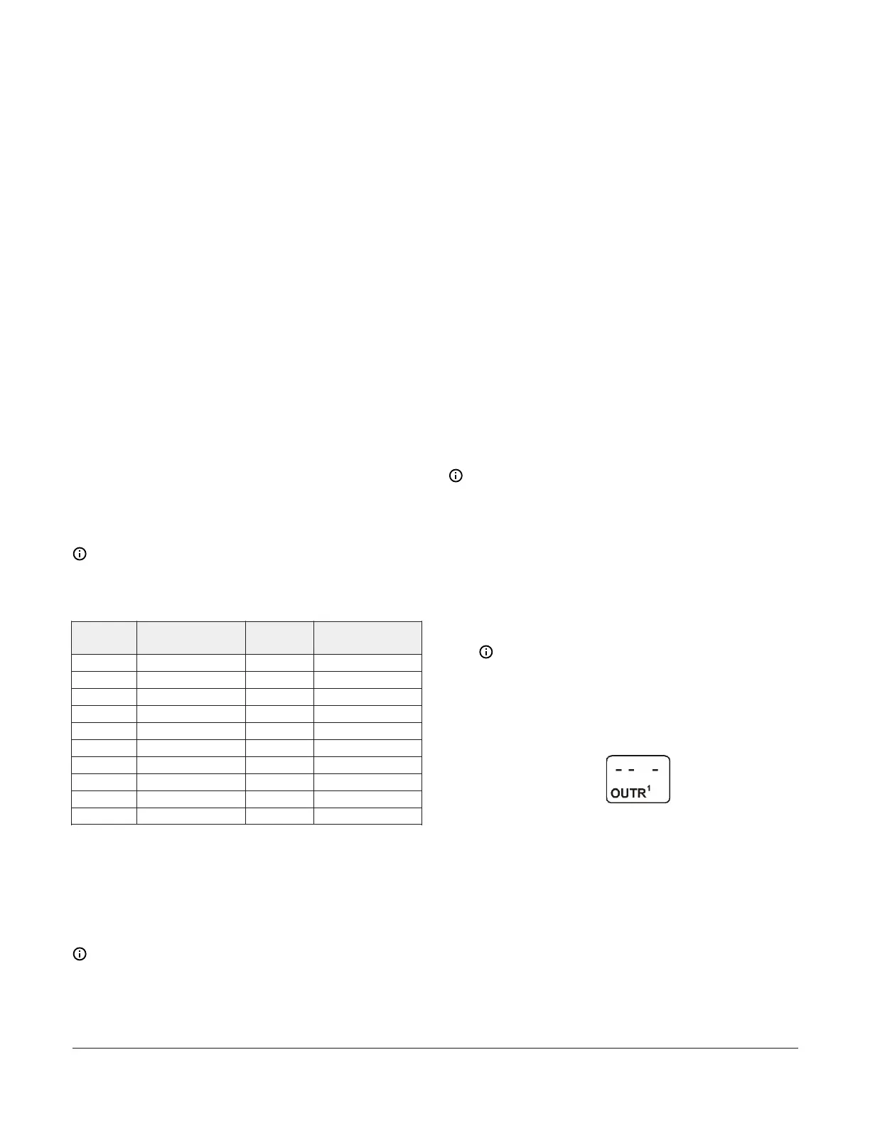
The following figure shows a Relay Output
Setup Start screen for Output 1.
Figure 16: Relay Output Setup Start screen
2. In the Sensor Selection screen, press Up or Down
to select the sensor that the output references. The
sensor you select here determines the output’s
setup parameters and values, including condition
type, unit of measurement, minimum control band,
default setup values, and setup value ranges for
several of the remaining output setup screens. If a
sensor is not selected, the remaining output setup
screens do not appear. If a sensor is already selected
for this output, the Sensor Selection screen does not
appear here and the Relay ON Selection (ON or dON)
screen appears instead.
System 450 Series Control Module with Ethernet Communications Installation Guide 11
 Loading...

