Figure 8: Password Protected Access screen
Setup Start screens are view-only screens, from which
you can access the setup screens for the sensors or the
displayed output; selections are not made in Setup Start
screens. The Sensor Setup Start screen is the first screen
displayed when you access the System 450 setup screens.
Note: The numerical order and type of Output
Setup Start screens are determined by the modules
selected for your System 450 control system and
their physical order in the control system module
assembly. See Setting up the Control System in the
UI for more information.
From the Sensor Setup Start screen, press M repeatedly
to scroll through the Output Setup Start screens for all of
the outputs in your control system. When a Setup Start
screen appears, press Next to go to the setup screens for
the sensors or the output displayed in the screen.
Note: In any Setup Start screen, you can return to
the Main screens by pressing both Up and Down
simultaneously. Also, the UI returns to the Main
screen after 2 minutes of inactivity in any screen.
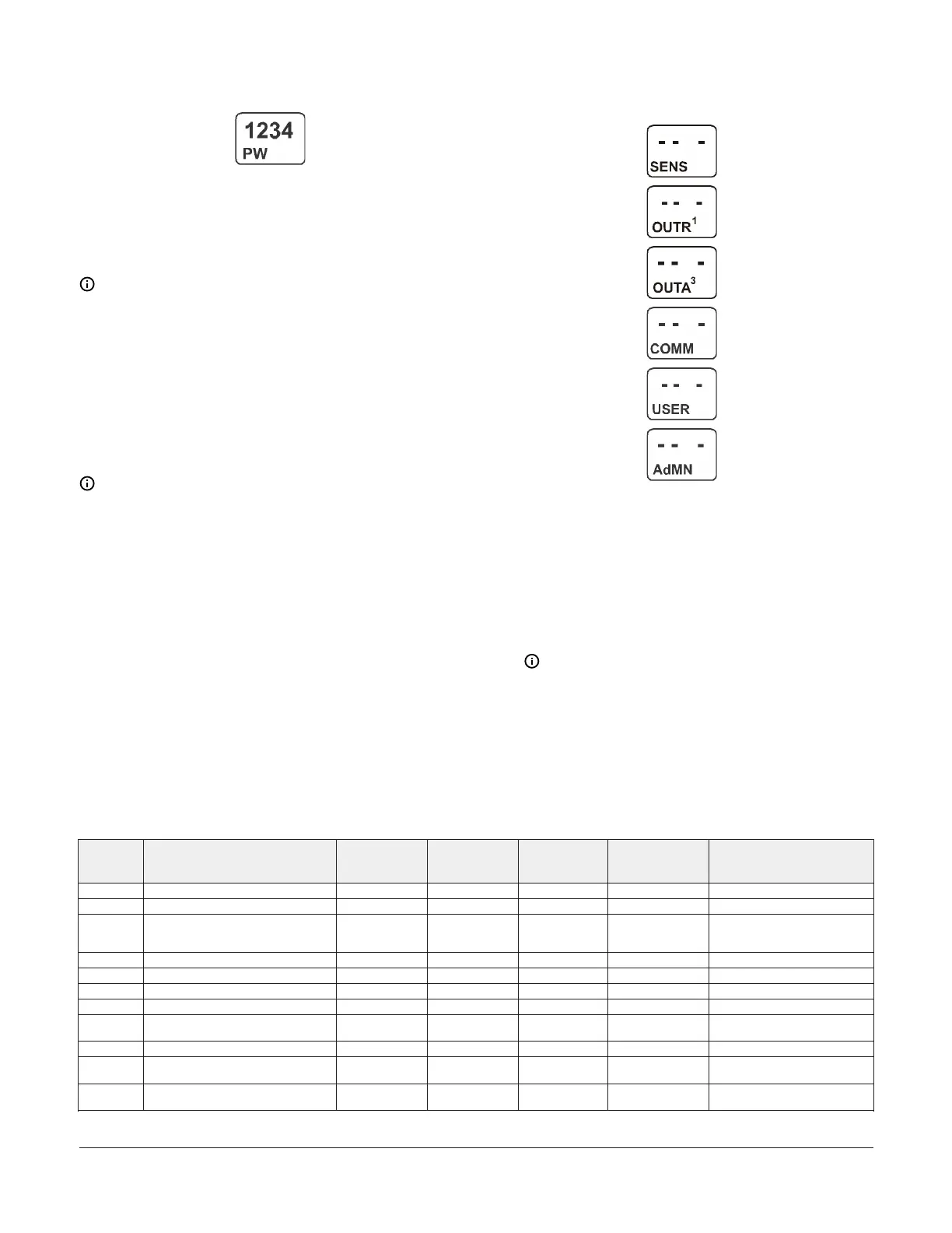
The following figure shows the Sensor, Relay Output 1,
Analog Output 3, Communications, User Password, and
Administrator Password Setup Start screens.
Figure 9: Setup Start screens
1. Apply power to your module assembly. After the
Startup screen appears briefly (displaying the control
module firmware version), the Main screen appears
on the LCD.
2. In the Main screen, press and hold Up and Down
simultaneously for 5 seconds to access the setup
screens and go to the Sensor Setup Start screen.
3. Press M repeatedly to scroll through the Output
Setup Start screens. See Figure 62.
Note: The UI returns to the Main screens after
2 minutes of inactivity in any screen in the UI.
Setting up System 450 Sensors
You must set up the input sensors for your control system before you can set up any of the outputs. To set up the input
sensors you must access the setup screens. See Accessing the System 450 Setup Start screens.
The Sensor Setup Start screen is the first screen displayed when you access the system setup screens.
Table 3: System 450 sensor types, setup values, and sensor or transducer product codes
Sensor type Unit of measurement value (condition/
units)
Effective sensing
range
1
Range of usable
values
1
Resolution
increment value
Minimum
proportional or
control band
2
Sensor product type number
2
°F °F (Temperature/degrees) -46 to 255 -40 to 250 1 1 A99x-xxx
°C °C (Temperature/degrees) -43 to 124 -40 to 121 0.5 0.5 A99x-xxx
rH % (Humidity/%RH) 1 to 100 10 to 95 1 2 HE-67Sx-xxxxx
HE-67Nx-xxxxx
HE-68Nx-0N00WS
P 0.25 INWC (Pressure/in. W.C.) -0.250 to 0.250 -0.225 to 0.250 0.005 0.010 DPT2650-R25B-AB
P 0.5 INWC (Pressure/in. W.C.) 0 to 0.5 0.025 to 0.5 0.005 0.010 DPT2650-0R5D-AB
P 2.5 INWC (Pressure/in. W.C.) 0 to 2.5 0.1 to 2.5 0.02 0.1 DPT2650-2R5D-AB
P 5 INWC (Pressure/in. W.C.) 0 to 5.0 0.25 to 5.0 0.05 0.25 DPT2650-005D-AB
P 8 bAR (Pressure/bar) -1 to 8 -1 to 8 0.05 0.1 P499RCP-401C
P598RCPSN401C
P 10 INWC (Pressure/in. W.C.) 0 to 10 0.5 to 10 0.05 0.2 DPT2650-10D-AB
P 15 bAR (Pressure/bar) -1 to 15 -1 to 15 0.1 0.2 P499RCP-402C
P598RCPSN402C
P 30 bAR (Pressure/bar) 0 to 30 0 to 30 0.1 0.4 P499RCP-404C
P598RCPSN404C
System 450 Series Control Module with Ethernet Communications Installation Guide 7
 Loading...

