1. In the Sensor Setup Start screen, press Next to go
to the first Sensor Type Selection screen (Sn-1) and
begin setting up the sensors in your control system.
The Sensor Setup Start screen is the first screen
displayed when you access the System 450 setup
screens. From the Sensor Setup Start screen you can
navigate to the Output Setup Start screens or the
Sensor Setup screens. See Figure 62.
Note: You must set up the input sensors before
you can set up the control system outputs.
The Sensor Setup Start screen is view-only;
selections are not made in Setup Start screens.
The following figure shows the Sensor Setup
Start screen with flashing dashes.
Figure 10: Sensor Setup Start screen
2. In the Sn-1 Sensor Type Selection screen, press
Up or Down to select the desired Sensor Type.
Press Next to save your selection and go to the Sn-2
Sensor Type Selection screen.
The Sensor Type you select for an input sensor
automatically determines the setup parame-
ters and values for each output that is set up to
reference that sensor. See Table 3 for informa-
tion about System 450 sensors or transducers,
Sensor Types, condition type, units of measure-
ment, minimum control band or proportional
band, setup values, value ranges, and product
code numbers.
Note: For outputs to operate properly, the
selected Sensor Type must match the sensor or
transducer model wired to the control module,
and the sensor or transducer must be wired to
the proper control module input terminals.
The following figure shows Sn-1 with the P 500
Sensor Type selected.
Figure 11: Sn-1 Sensor Type Selection screen
3. In the Sn-2 Sensor Type Selection screen, press
Up or Down to select the desired Sensor Type.
Press Next to save your selection and go to the Sn-3
Sensor Type Selection screen.
Note: If your control system does not use three
input sensors, simply press Next while the two
dashes are flashing in a Sensor Type Selection
screen to save no Sensor Type and go to the
next setup screen.
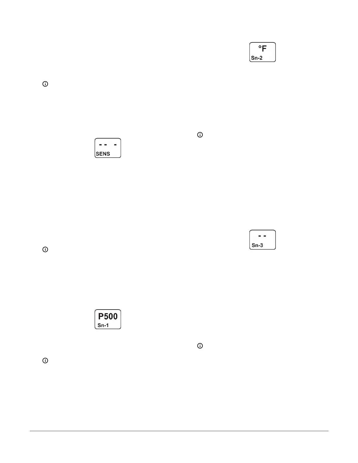
The following figure shows Sn-2 with the °F
Sensor Type selected.
Figure 12: Sn-2 Sensor Type Selection screen
4. In the Sn-3 Sensor Type Selection screen, press Up
or Down to select the desired Sensor Type. Press
Next to save your selection and either:
- go to the Temperature Offset Setup screen
for the first temperature sensor in your
system.
- return to the Sensor Setup Start screen,
if your control system has no temperature
sensors.
Note: On System 450 control modules with
network communications, if you select the
same Sensor Type for Sn-1 and Sn-2, two
additional functional sensors (Sn-d and HI-2)
are available for selection when you set up
the control system outputs. If you select the
same Sensor Type for Sn-1, Sn-2 and Sn-3,
then functional sensor HI-3 is also available for
selection when you set up outputs. See High
Input-Signal selection and Differential control
for more information.
The following figure shows Sn-3 with the no
Sensor Type selected.
Figure 13: Sn-3 Sensor Type Selection screen
5. In the Temperature Offset Selection screen, press
Up or Down to select the desired temperature
offset value. Select a temperature offset for the
temperature inputs (only) in your control system.
Sensor Type °F enables an offset of +/- 5°F in 1
degree increments. Sensor Type °C enables an offset
of +/- 2.5°C in 0.5 degree increments.Press Next:
- to go to the next Temperature Offset
Selection screen (if there are additional
temperature sensors in your control system)
and repeat this step for each temperature
sensor.
- to return to the Sensor Setup Start screen.
Note: The temperature offset changes the
displayed temperature value by the selected
offset value.
The following figure shows an OFFS value
of -3 (°F) for Sensor 2. Therefore, a sensed
temperature value of 75 (°F) at Sensor 2 is
displayed as 72 (°F).
System 450 Series Control Module with Ethernet Communications Installation Guide 9
 Loading...

