You cannot make any changes to the system configurations on the System Overview page. You must log in to the web
UI with the assigned username and password and then go to the sensor and output configuration pages to change your
control system parameters and values.
This control system example uses the following input sensors and outputs:
• a pressure sensor (Sn-1) to control the motor speed of two condenser fans with analog outputs (OUTA1 and OUTA2)
• a temperature sensor (Sn-2) to control the cooling equipment (using Relay Output OUTR3) that maintains room
temperature
• a humidity sensor (Sn-3) to control the humidification equipment (using Relay Output OUTR4) to maintain the room
humidity
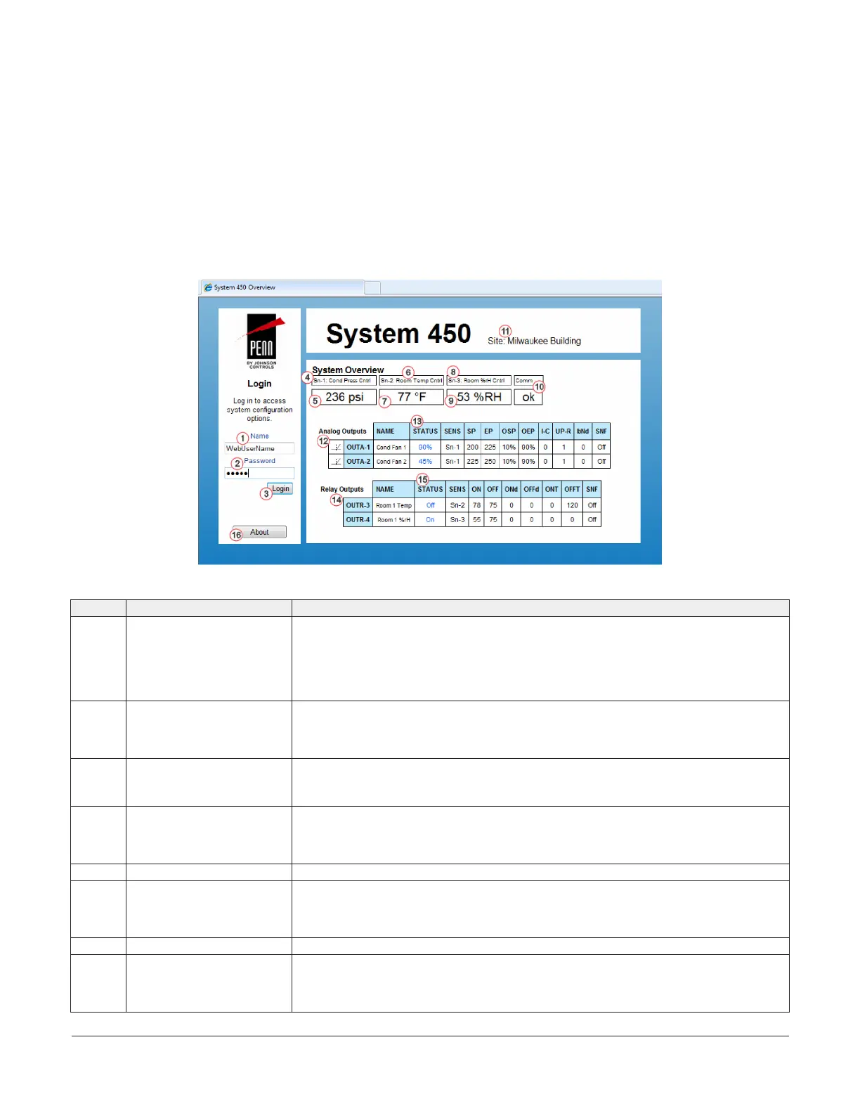
Table 7 provides descriptions, user actions, and references for the items called out in Figure 63.
Figure 63: System 450 System Overview page example
Table 7: System 450 web UI Overview page descriptions, user actions, and references
Callout Identifier item name User actions, descriptions, references
1 Name login field Enter the assigned System 450 web username here.
You can assign a web username in the WebUserName: field in the Web Server section on
the Network Configuration page. See Network Configuration page for more information
about assigning a username.
In this example, WebUserName is entered as the assigned login name. The default web
username is System450User1.
2 Password login field Enter the assigned System 450 web password here.
You can assign a web password in the Web Password: field in the Web Server section on the
Network Configuration page. See Network Configuration page.
In this example, a password is entered. The default web password is Wx9jc3.
3 Login button After entering the assigned web username and web password, click Login to log in to the
System 450 web UI. The System Configuration page appears. See System Configuration page
for more information.
4 Sn-1: Sensor 1 name Identifies the Sn-1 (Sensor 1) and displays the assigned Sn-1 name.
You have the option to assign a sensor name for Sn-1 in the Name field in the Sn-1: Sensor 1
section on the Sensor Configuration page.
In this example, the assigned sensor name for Sn-1 is Cond Press Cntrl.
5 Sn-1 status Displays the current condition status sensed at Sn-1.
6 Sn-2: Sensor 2 name Identifies the Sn-2 (Sensor 2) and displays the assigned Sn-2 name.
You have the option to assign a sensor name for Sn-2 in the Name field in the Sn-2: Sensor 2
section on the Sensor Configuration page.
In this example, the assigned sensor name for Sn-2 is Room Temp Cntrl.
7 Sn-2 status Displays the current condition status sensed at Sn-2.
8 Sn-3 Sensor 3 name Identifies the Sn-3 (Sensor 3) and displays the assigned Sn-3 name.
You have the option to assign a sensor name for Sn-3 in the Name field in the Sn-3: Sensor 3
section on the Sensor Configuration page.
In this example, the assigned sensor name for Sn-3 is %rH Cntrl.
System 450 Series Control Module with Ethernet Communications Installation Guide26
 Loading...

