System 450™ Series Modular Control Systems with Standard Control Modules Technical Bulletin
12
Binary Input Sensor
You can connect a binary input (dry contacts) to any of the three System 450 control module inputs (Sn1, Sn2, or
Sn3) and control output relays in your control system based on the binary input state (open or closed).
An input (Sn1, Sn2, or Sn3) set up as a binary input can be referenced by relay outputs only. Sensors set up as
binary inputs are not available for selection when you set up an analog output. When you select a sensor in the UI
that is set up as a binary input, the On value and the OFF value selection screens are not available in the Relay
Output Setup screens. See Binary Input Control for Relay Outputs
on page 14 for more information.
System 450 Functional Sensors
System 450 control modules also enable several functional sensors based on the input from one or more of the
hard-wired sensors in your control system. Selecting a functional sensor for an output on a System 450 control
system enables the differential or high signal selection control features on the output.
System 450 standard control modules provide for three functional sensors:
• When Sn-1 and Sn-2 are set up as the same Sensor Type, the High Input Signal Selection functional sensor
(HI-2) and Differential Control functional sensor (Sn-d) are enabled and available in the Sensor Selection
screens for each output in the control system.
• When Sn-1, Sn-2, and Sn-3 are the same Sensor Type, the High Input Signal Selection functional sensor (HI-
3) is also enabled and available.
P 750 PSI (Pressure/psi) 0 to 750 150 to 750 2 6 P499RAP-107C
P499RAP-107K
P499RCP-107C
P499RCP-107K
P598RAPSN107C
P598RAPSN107K
P598RCPSN107C
P598RCPSN107K
HIF F (Temperature/degrees) -50 to 360
-40 to 350
4
1 1 TE-631x, TE-6000-x,
TE-68NT-0N00S
HIC C (Temperature/degrees) -45.5 to 182
-40 to 176
4
0.5 0.5 TE-631x-x
TE-6000-x
TE-68NT-0N00S
bin
Open or Closed
5
N/A N/A N/A N/A N/A
1. Because of the way that the System 450 Differential Sensor (Sn-d) is set up and calculated with two identical sensors (Sn-
1 and Sn-2), the Range of Usable Values is twice as large as a single sensor. See Table 5 on page 24 for the Range of
Usable Values when an output references Sn-d.
2. See Table 14 through Table 23 in Repair and Ordering Information
on page 55 for more information on the compatible
sensors for the System 450.
3. See Setting up Control System Outputs on page 45 for information on setting up System 450 outputs that reference the
P110 Sensor Type.
4. Many of the temperature sensors that can be set up as HI°F or HI°C Sensor Types are not designed for use across the
entire Range of Usable Values for HI°C HI°F and Sensor Types. See Table 15, Table 16, and Table 17 or refer to the
Technical Specifications
on page 63 to determine the sensor hardware configuration and temperature. The TE-6000-6
Nickel Sensor is the only sensor designed for use over the entire temperature range.
5. Selecting the bin Sensor Type for a sensor (Sn-1, Sn-2, or Sn-3) sets up the input to control relay outputs (only) based on
the state of the binary input contacts (open or closed) connected to the sensor input (Sn1, Sn2, or Sn3). See Binary Input
Control for Relay Outputs on page 14 for more information.
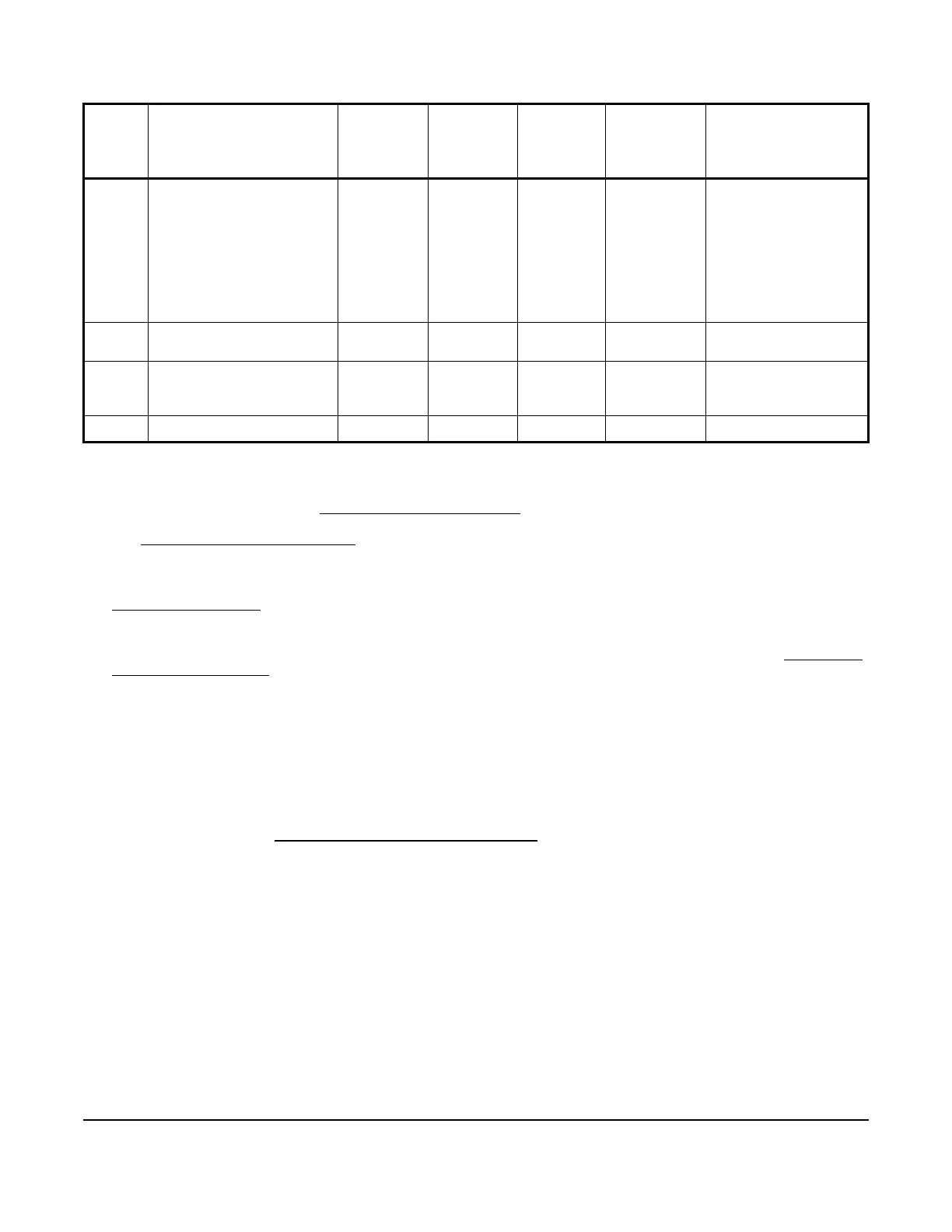
Table 2: System 450 Sensor Types, Setup Values, and Sensor/Transducer Product Codes (Part 3 of 3)
Sensor
Type
Unit of Measurement
Value
(Condition/Units)
Effective
Sensing
Range
Range of
Usable
Values
1
Resolution
Increment
Value
Minimum
Proportional
or Control
Band
Sensor Product Type
Number
2
 Loading...

