4
IntelliCenter Control System Indoor Control Panel Installation Guide
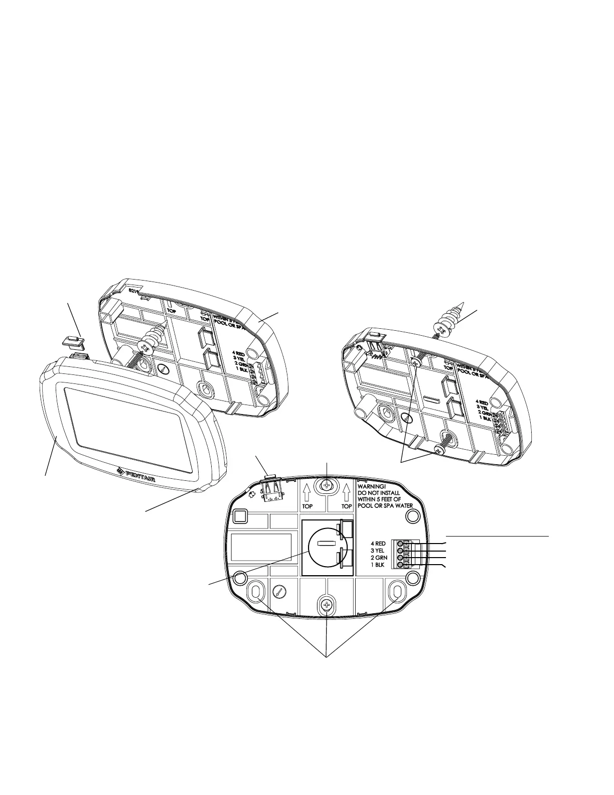
3. Mount the Indoor Control Panel backplate on the mounting surface. Align the backplate screw
holes with the backplate screw holes and secure the backplate with the screws (see illustration on
previous page).
4. At the Indoor Control Panel, strip the leads of the communication cable wires back ¼ in. Insert the
wires into the connector screw terminals (provided in the kit). Using a small flat-blade screwdriver,
secure the wires with the terminal screws. Make sure to match the color-coding of the wires:
GND = Black, Green = -DT, Yellow = +DT, and Red = +15. Connect the screw terminal connector
onto the transceiver circuit board. The preferred wire color scheme is: Red, Yellow, Green, and Black.
5. Mount the Indoor Control Panel cover over backplate and snap in place to secure.
6. Run a UL approved four conductor cable (22 AWG) from the Indoor Control Panel to the Load
Center. NOTE: Use 18 AWG conductor cable for distances longer that 200 ft.
Connecting the Communication Cable to the Indoor Control Panel
Front cover
Back plate
Mounting hole
Cut hole in mounting
surface for
communication
cable
Unsnap from here to
remove front cover
Mounting hole
Screw terminal pin-outs
Pin 1 GND / BLACK
Pin 2 -DT / GREEN
Pin 3 + DT / YELLOW
Pin 4 15 V / RED
Plastic
anchor (x4)
USB Port (*)
Mounting screws (x2)
USB Port
cover plug
Note: (*) Use the USB port to upgrade the IntelliCenter Control System rmware. See page 7.

 Loading...