2
IntelliCenter Control System Indoor Control Panel Installation Guide
IntelliCenter™ Automation System For Pool and Spa Indoor Control Panel
Installation
SWITCH OFF AC POWER TO THE INTELLICENTER SYSTEM LOAD CENTER
BEFORE MAKING ANY CONNECTIONS.
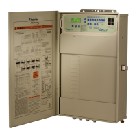
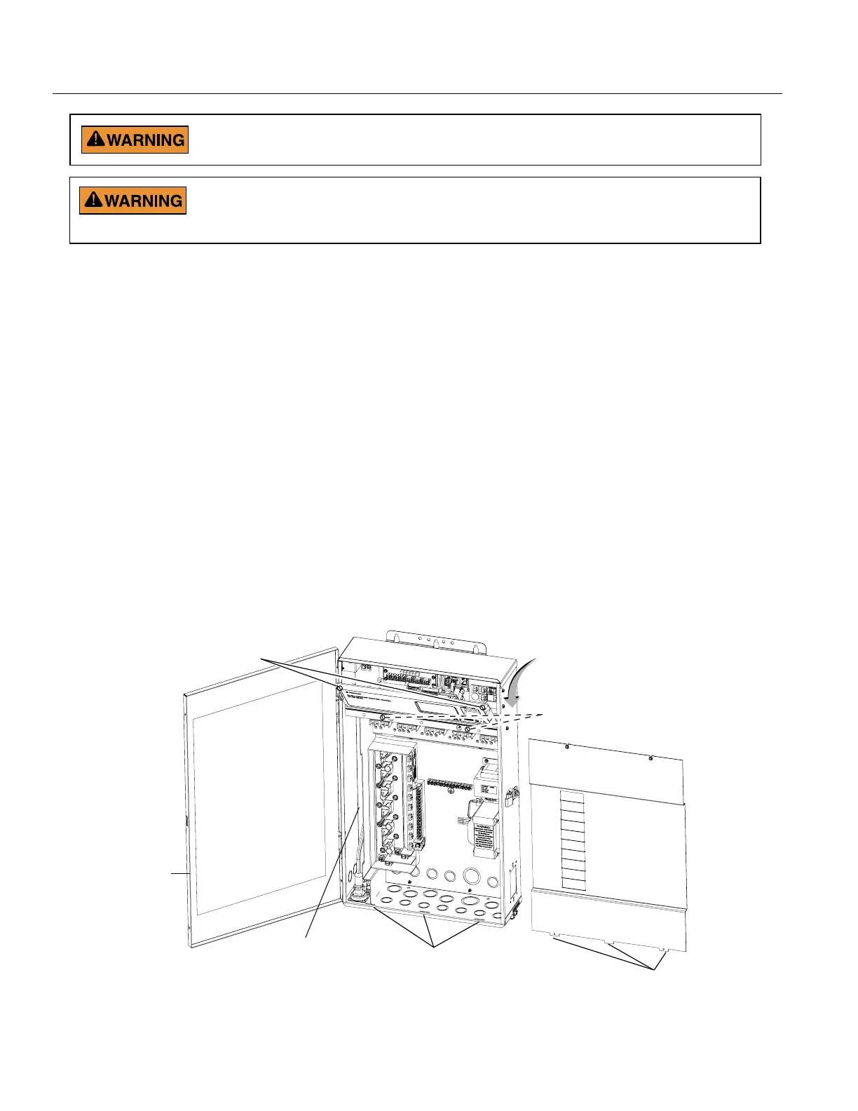
IntelliCenter Automation System Load Center (front view)
(High Voltage Cover Panel removed)
BEFORE REMOVING THE HIGH VOLTAGE COVER PANEL FROM THE
LOAD CENTER OR POWER CENTER ENCLOSURE SWITCH OFF THE
POWER AT THE HOUSE MAIN CIRCUIT BREAKER BOX.
1. Switch OFF AC power to the enclosure at the main house panel circuit breaker.
2. Unlatch the front door latch and open the front door. Remove the two retaining screws from the
High Voltage Cover Panel and remove the panel.
3. Loosen the two retaining screws securing from the top edge of the Outdoor Control Panel. Fold
down the Outdoor Control Panel to access the circuit board sockets connectors for the electrical
connections.
4. FROM THE INDOOR CONTROL PANEL LOCATION: Route the four conductor RS-485 connection
cable from the Indoor Control Panel location into the Load Center lower plastic grommet, up
through the low voltage raceway to the system circuit board.
5. Connect the communication cable conductors to the COM PORT (J15 or J16) connector.
See page 5.
7. After Connecting the RS-485 cable to the Indoor Control Panel (pages 3-6): When finished
connecting the communication cable to the RS-485 connector on the main circuit board, close the
hinged control panel and secure it with the two retaining screws. Reinstall the High Voltage Panel:
Insert the panel’s three tabs into the lower slots on the enclosure. Secure the panel with the two (2)
retaining screws.
Close the front door and secure with the latch.
LOW VOLTAGE
RACEWAY
High Voltage Cover Panel Tabs (3)
Remove two (2) retaining
screws securing High Voltage
Cover Panel
Front door
High Voltage Cover Panel slots (3)
Flip down the Outdoor Control Panel
to access circuit board and low
voltage compartment
Loosen Outdoor Control
Panel retaining screws

 Loading...