I/O Connections 17
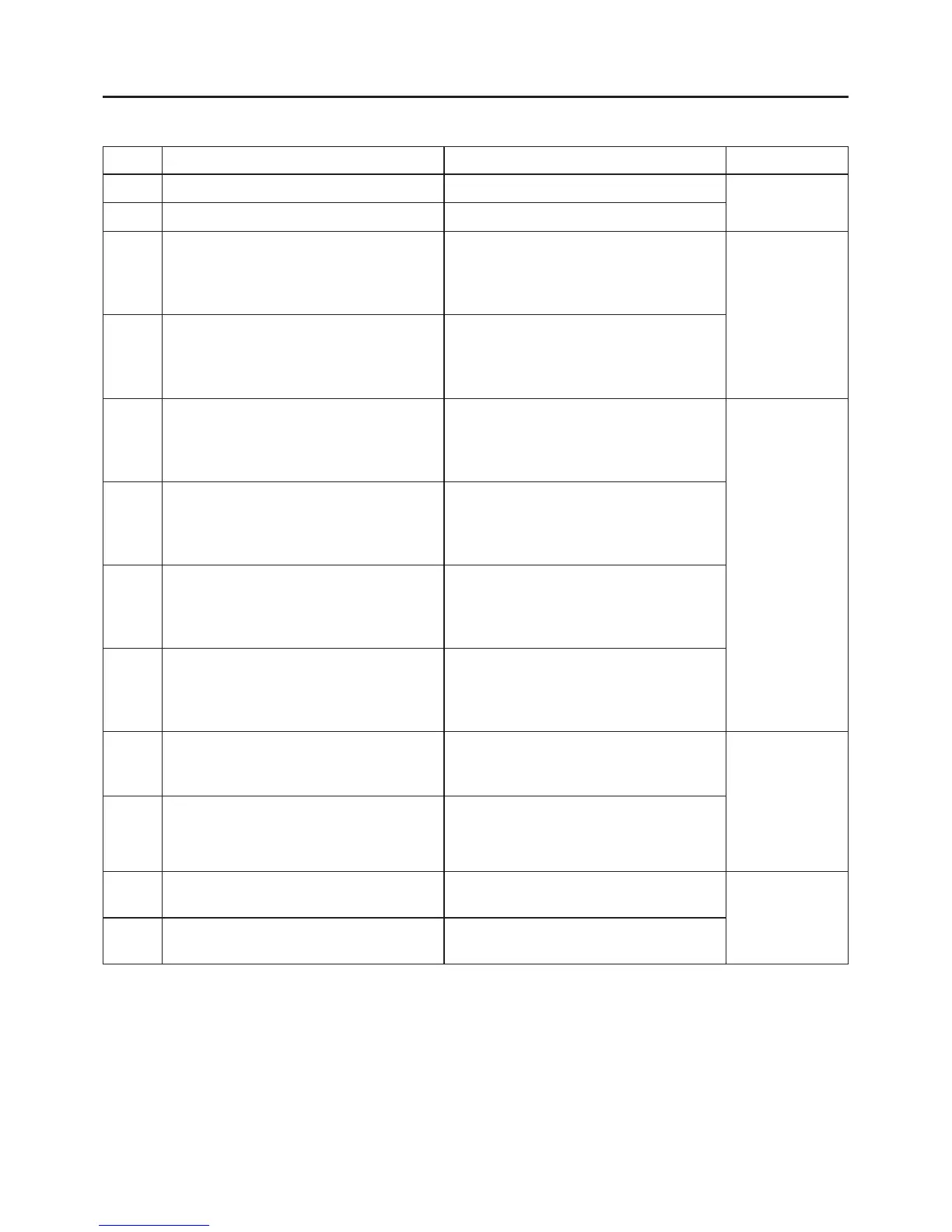
Table 6 - I/O Function, Connections, Ratings
Label Function Connection Rating
AI+
Positive connection for transducer Red transducer wire
24 Volt
(supplied)
AI-
Negative connection for transducer Blacktransducerwire
V+
Positive side of 24 volt power supply.
Used to power external devices.
Positive side of 24V external device, i.e.,
flow switch, moisture sensor, alternator,
etc. Need to complete the circuit with V-.
See Figures 15 and 17.
40mA maximum
output
V-
Negative side of 24 volt power supply.
Used to power external devices.
Typically to I1-, I2-, or O1+. Used with
a flow switch, moisture sensor, alternator,
etc. Need to complete the circuit with V+.
See Figures 15 and 17.
I1+
Positive connection of Digital Input 1.
Connect when using an external device to
control Drive.
From an external device i.e., flow switch,
moisture sensor, alternator, etc. Requires
complete circuit connection with I1-. See
Figures 15 and 16.
Accepts 24VDC
and up to
230VAC
I1-
Negative connection of Digital Input 1.
Connect when using an external device to
control Drive.
Can be from V- or from the negative side
of an external power supply. Requires
complete circuit connection with I1+. See
Figures 15 and 16.
I2+
Positive connection of Digital Input 2.
Connect when using an external device to
control Drive.
From an external device, i.e., flow switch,
moisture sensor, alternator, etc. Requires
complete circuit connection with I2-. See
Figures 15 and 16.
I2-
Negative connection of Digital Input 2.
Connect when using an external device to
control Drive.
Can be from V- or from the negative side
of an external power supply. Requires
complete circuit connection with I2+. See
Figures 15 and 16.
O1+
Output relay (dry contacts) connection.
Programmed to close when pump is
Running or Faulted.
Positive wires of an external device. See
Figures 17 and 18.
Accepts up
to 5Amps at
24VDC and
8Amps at up to
230VAC
*Only non-
inductive loads
O1+
Output relay (dry contacts) connection.
Programmed to close when pump is
Running or Faulted.
Positive wires of an external device. See
Figures 17 and 18.
P
Positive connection of an RS-485
communication device (see Figure 19).
Positive wire from RS-485 device.
Per RS-485
Standard
N
Negative connection of an RS-485
communication device (see Figure 19).
Negative wire from RS-485 device.
 Loading...