17
063/E006 63/600 15 28 48
125/E013 125/1300 15 28 48
250/E025 250/2500 15 28 48
500/E051 500/5100 15 28 48
1000/E091 1000/9100 24 45 80
2000/E171 2000/17700 53 100 180
6.2.2 Close limit configuration by position
Enter set up configuration:
• Move switch SW4 to position 2
• Move switch SW6 to position 1
• Move switch SW3 to position ON
• Confirm by pushing ENTER pushbutton SW5
• When pushing SW5, the red LED switches on
for confirmation
• Exit set up configuration, moving switch
SW3 to position 1 or proceed with the next
parameter
6.2.4 Open limit configuration by position
• Move switch SW4 to position 3
• Move switch SW6 to position 1
• Move switch SW3 in ON
• Confirm by pushing ENTER pushbutton SW5
• When pushing SW5, the red LED switches on
for confirmation
• Exit set up configuration, moving switch
SW3 to position 1 or proceed with the next
parameter
6.2.5 Open limit configuration
• Drive the actuator to open position using the
handwheel.
• Move switch SW 4 to position 1
• Move switch SW 6 to position 0
• Move switch SW 3 to position ON
• Confirm by pushing ENTER pushbutton SW5
• When pushing SW5, the red LED switches ON
for confirmation
• Exit set up configuration, moving switch
SW3 to position 1 or proceed with the next
parameter
6.2.6 Close limit configuration by torque
• Move switch SW4 to position 2
• Move switch SW6 to position 0
• Move switch SW3 to position ON
• Confirm by pushing ENTER pushbutton SW5
(red LED switch on)
• Operate the actuator to closing direction by
local/remote control and wait until it stops by
torque
• When the setting is completed, the red LED
switches off
• Exit set up configuration, moving switch
SW3 to position 1 or proceed with the next
parameter
6.2.7 Open limit configuration by torque
• Move switch SW4 to position 3
• Move switch SW6 to position 0
• Move switch SW3 to position ON
• Confirm by pushing ENTER pushbutton SW5
(red LED switch on)
• Operate the actuator to opening direction by
local/remote control and wait until it stops by
torque
• When the setting is completed, the red LED
switches off
• Exit set up configuration, moving switch
SW3 to position 1 or proceed with the next
parameter
IMPORTANT
During the new stroke limit setup, the minimum
range between open and close limit position has
to be at least 40 degree of the valve position; if the
above condition is not respected, the setup will
not be successful and stroke limit error alarm will
be signalized (red LED blinking).
The red LED will continuously flash when the
actuator is in setup functionality (dip switch SW3
in ‘on’ position) and rotary switches SW4 and SW6
are in one of the following positions:
a. SW4=3 and SW6=0
(stroke limit of open configuration by torque)
b. SW4=2 and SW6=0
(stroke limit of close configuration by torque)
c. SW4=1 and SW6=0
(stroke limit of open configuration by position)
d. SW4=0 e SW6=0
(stroke limit of close configuration by position)
The alarm is then reset by:
a. Switching off and on the actuator
b. Doing a new correct stroke limit setup in one of
the 4 possible combinations.
WARNING
In configuration phase, touch only the
configuration area of the logic board; don’t touch
the actuator in its other parts.
6.2.3 Close limit configuration
• Drive the actuator to the closed position using
the handwheel
• Move switch SW4 to position 0
• Move switch SW6 to position 0
• Move switch SW3 to position ON
• Confirm by pushing ENTER pushbutton SW5
• When pushing SW5, the red LED switches on
for confirmation
• Exit set up configuration, moving switch
SW3 to position 1 or proceed with the next
parameter
6.2.8 Stroking time selection in closing
• Enter set up configuration: move switch SW3
to position ON (configuration function)
• Move switch SW4 to position 4
• Move switch SW6 to positions 4, 6, 8 for the
requested stroking time according to the
table below
OPERATING TIMES
Model
Nominal torque
(Nm / lb.in.)
Operating time (secs 90°) at selected step
8 6 4
• Push ENTER pushbutton SW5 to confirm
• When pushing SW5, the red LED switches on
for confirmation
• The selected stroking time in closing is now
set
• Exit set up configuration (move switch
SW3 to position 1) or proceed with the next
parameter
6.2.9 Stroking time selection in opening
• Enter set up configuration: move switch SW3
to position ON (configuration function)
• Move switch SW4 to position 5
• Move switch SW6 to positions 4, 6, 8 for the
requested stroking time according to the
table below
• Push ENTER pushbutton SW5 to confirm
• When pushing SW5, the red LED switches on
for confirmation
• The selected stroking time in opening is now
set
• Exit configuration (move switch SW3
to position 1) or proceed with the next
parameter
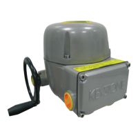
KEYSTONE EPI-2 QUARTER-TURN ELECTRIC ACTUATOR
InstallatIon and MaIntenance InstructIons
NOTE: Time is guaranteed with +/- 10% tolerance on 90° stroke
 Loading...
