23800 /361
23800 MX
Disassembly procedure
1. Peel off Body coverings (A19 & A20)
2. Remove Bottom cover (A400), Connector seat (A34) and Tripod screw (All).
CSS 1.7 x 2.2 x 3, CSM 1.7 x 3.5 x 2
3. Remove Top cover (A300)
a.) Retainer screw (Left handed)
Winding lever assembly (C300)
Cover ring B (A329)
b.) Shutter dial— ASA100, 1/1000
Shutter dial screw (E231) — 23800K-E321A
Shutter dial assembly (0-E223), Hook pin (E228)
Speed dial assembly (0-E229)
c.) Knob assembly (0-D1)
Nut (D12)—23110-D16-1-A
Cover ring (D7)
• d.) Top cover retainer screw (A15 x 2)
CSS 1.7 x 2.2 x 2
Top cover assembly (A300)
4. Unsolder 7 lead wires
5. Front board plate assembly (A100)
— Not necessary to cock self-timer.
Cover (A24)
0.1mm washers are underneath the Front board plate.
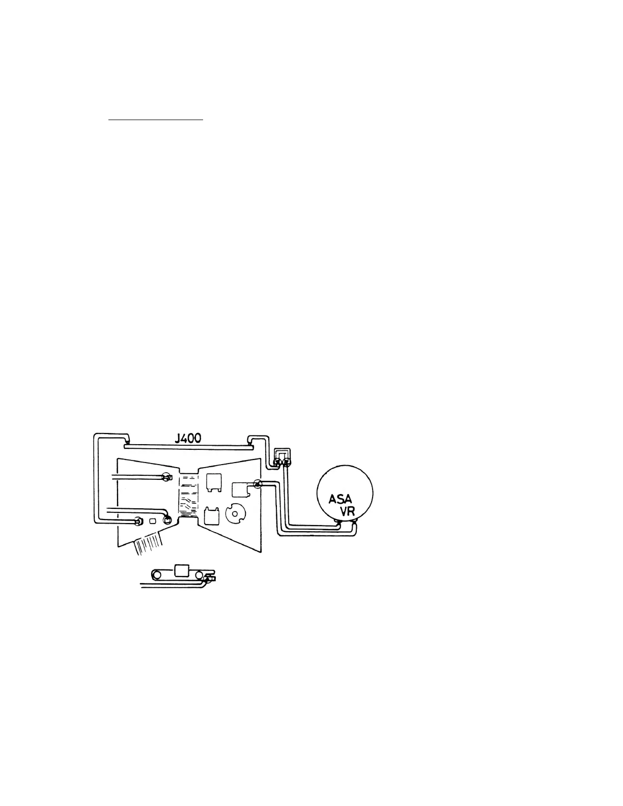
6. Sv resistor assembly (J300)— Retainer screws (E208 x 2)
7. Hot shoe contact (3204) — Hot shoe contact screw (3209 x 2)
8. P.C.board retainer plate (J205) — P.C.board retainer screw (J208), Spring (J206)