2018-07
20
LB Remote I/O System
Product Specifications
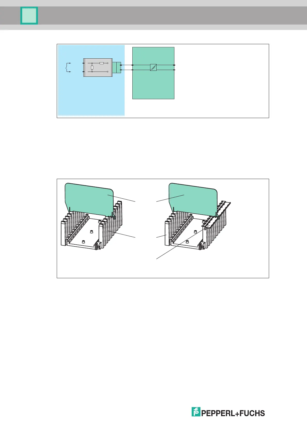
Figure 2.26 Block diagram of the F-NR2-Ex1 resistor network
2.6.3 Separation between Intrinsically Safe and Non-Intrinsically Safe I/O
Modules
The separation wall is attached to the backplane between I/O modules with intrinsically safe
circuits and I/O modules with non-intrinsically safe circuits to ensure a clearance of 50 mm
between intrinsically safe circuits and other circuits. The separation wall can be installed on
both backplanes with and without a label carrier.
Figure 2.27 Separation wall on the LB9182A
Zone 1, 2
F-NR2-Ex1
10 kΩ
1.5 kΩ
2-
1+
-
+
Backplane
Separation
wall
Label carrier