LB Remote I/O System
Installation
2018-07
25
X40 Terminal Assignment
Auxiliary energy for 4-channel digital outputs LB6*10* ... LB6*15* can be connected via the
booster connection.
X40.1 = 0 V
X40.2 = + 24 VDC (SELV/PELV)
X40.3 = earth
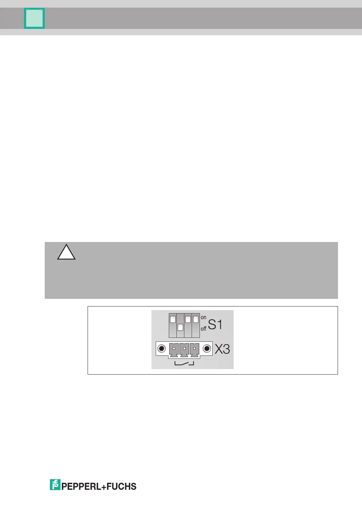
S1 Switch Positions and X3 Terminal Assignment
The S1 switch and X3 terminal control the bus-independent deactivation of the I/O modules.
The bus-independent deactivation of the I/O modules only works for I/O modules equipped
with a shutdown input. I/O modules with and without a shutdown input can be installed on the
same backplane; however, only the I/O modules that are equipped with a shutdown input are
controlled by the bus-independent deactivation.
If I/O modules equipped with a shutdown input are installed on the backplane, these modules
can be deactivated using an external switch, for example.
Figure 3.3 X3 terminals and S1 function switches
1X40: booster connection
2S1: function switch
3X3: bus-independent deactivation of the I/O modules
4X2: 24 VDC redundant power supply (SELV/PELV)
5X1: 24 VDC power supply (SELV/PELV)
Caution!
Damage to Equipment
Handling the connections improperly can damage the backplane.
Never supply a control voltage to X3.2.
Only operate multiple adjacent backplanes using a common control voltage or a common
contact to avoid equalizing currents.