9
GT 24 Girder
Bearing pressure:
Reaction force perm. A = b x L
eff
x k
c
x perm. m
D
b = support width
L
eff
= effective support length
= L
A
+ 2 x 3 cm, but
≤ 2 x L
A
Design-typical lateral pressure coefficient for
support directly under the nodes k
c,90,n
= 1.45
support between the nodes k
c,90,m
= 1.0
Bearing pressure perm. m
D
= 1.24 N/mm²
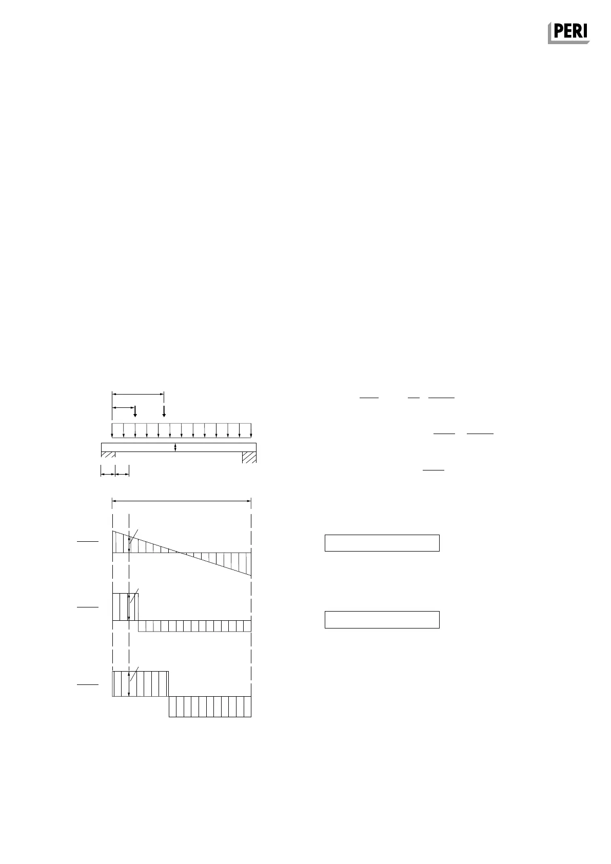
Specified shear forces
For the design, the shear forces (external loads)
may be reduced as follows:
In addition, the shear force
Q = Q
q
+ Q
F1
+ Q
F2
must be verified directly over the support
The following applies for cantilever
beams: I = 2 x I
k
Q
q,red
=
q x l
x
(
1 –
L
A
–
48 cm
)
2 l l
e
1
< 60 cm: Q
F1,red
= F
1
x
I – e
1
x
e
1
I 60 cm
e
2
> 60 cm: Q
F2
= F
2
x
I – e
1
I
Q
red
= Q
q,red
+ Q
F1,red
+
Q
F2
Q
red
≤ perm. Q = 13 kN
Q ≤ perm. Q
n
= 16 kN
e
2
e
1
F
1
F
2
q
h
L
A
24
I
Q
q
Q
F1
Q
F2
q x I
2
F
1
x
I – e
1
I
F
2
x
I – e
2
I
A2 Components
MULTIFLEX Girder Slab Formwork
Assembly Instructions for Standard Configuration