10
Permissible internal forces and reaction forces:
Permissible shear force perm. Q = 11.0 kN
Permissible reaction force perm. A = 22.0 kN
Permissible bending moment perm. M = 5.0 kNm
Bending stiffness EI = 460 kNm²
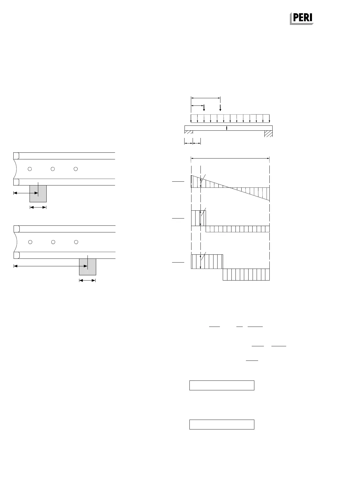
End supports for single spans and
continuous girders
perm. A = 16 kN
min. 15 cm
l
A
perm. A = max. perm. A = 22 kN
45 cm
l
A
The projecting length of the girder must be at least
15 cm.
Depending on the projecting length of the girder
between the two values A = 16 kN and max. perm.
A = 22 kN, the permissible bearing load can be lin-
early interpolated.
For transferring the maximum reaction force into
the VT 20 girder, the support length l
A
must be at
least 13.5 cm.
Specified shear forces
For the design, the shear forces (external loads)
may be reduced as follows:
In addition, the shear force Q
= Q
q
+ Q
F1
+ Q
F2
must be verified directly over the support.
The following applies for cantilever beams:
I = 2 x I
k
Q
q,red
=
q x l
x
(
1 –
L
A
–
40 cm
)
2 l l
e
1
< 50 cm: Q
F1,red
= F
1
x
I – e
1
x
e
1
I 50 cm
e
2
> 50 cm: Q
F2
= F
2
x
I – e
1
I
Q
red
= Q
q,red
+ Q
F1,red
+
Q
F2
Q
red
≤ perm. Q = 11 kN
Q ≤ perm. Q
n
= 16 kN
e
2
e
1
F
1
F
2
q
h
L
A
20
I
Q
q
Q
F1
Q
F2
q x I
2
F
1
x
I – e
1
I
F
2
x
I – e
2
I
Bearing pressure:
Reaction force perm. A = b x L
eff
x k
c
x perm. m
D
b = support width
L
eff
= effective support length
= L
A
+ 2 x 3 cm, but ≤ 2 x L
A
Design-typical lateral pressure coefficient with k
c,90,n
= 1.15
Bearing pressure perm. m
D
= 1.24 N/mm
2
A2 Components
VT 20 Girder
MULTIFLEX Girder Slab Formwork
Assembly Instructions for Standard Configuration