11
A2 Components
4a 4b
2a 2b
3a 3b
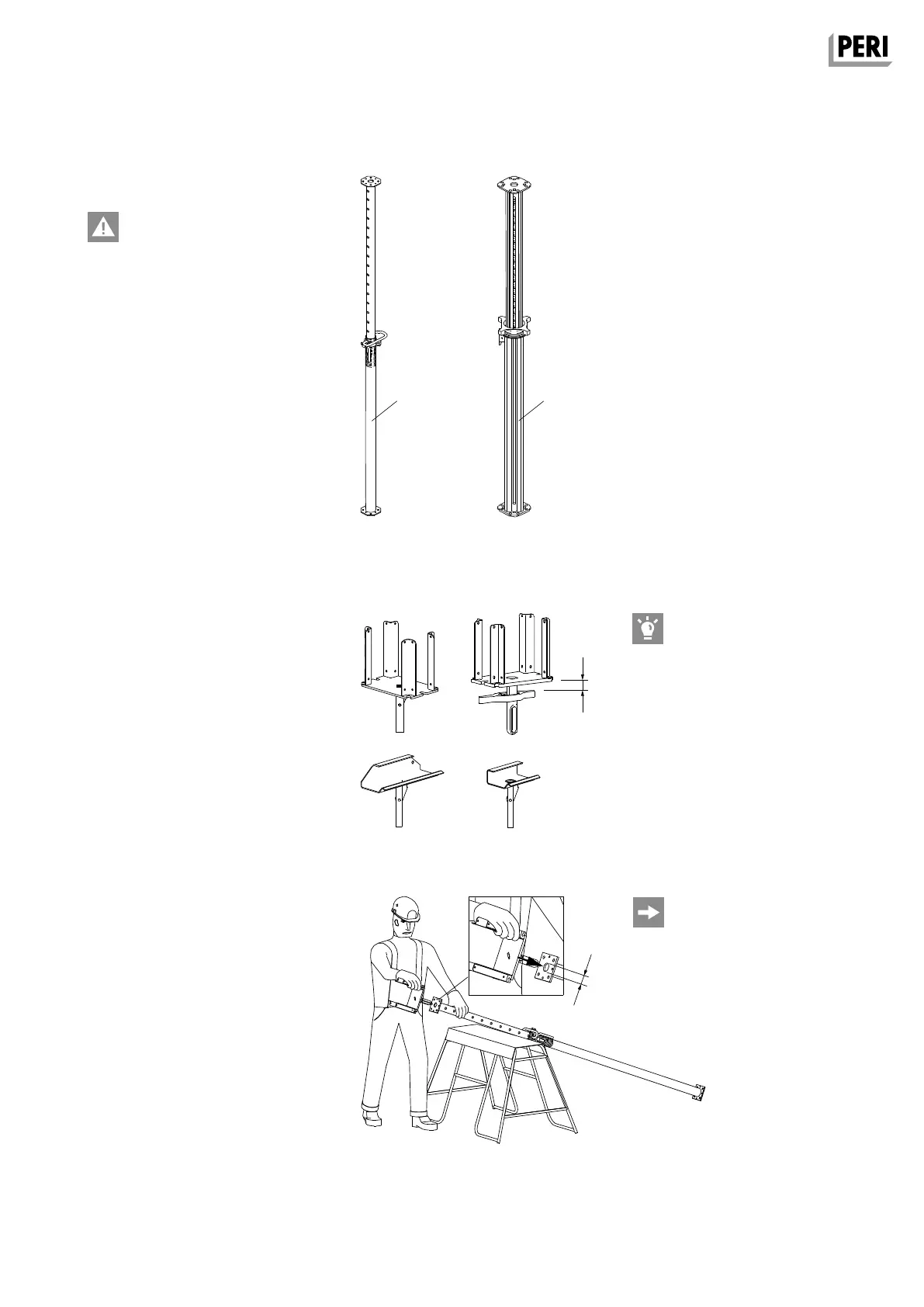
Slab Props
Loads from the MULTIFLEX slab
formwork must be safely transferred
into the ground.
Do not exceed the permissible
load-bearing capacities!
PERI Shoring
– Steel Tube Props PEP (4a).
– Aluminium Props MULTIPROP MP (4b).
– Shoring Towers MULTIPROP System,
PERI UP, PD 8, ST 100 (not shown).
See corresponding Assembly Instruc-
tions.
The formwork supports fit all standard
slab props with 40 mm hole diameters.
When marking out the prop, pay
attention to the required lowering
height (min. 40 mm).
Fig. A2.03
40
40
Fig. A2.01
Fig. A2.02
Formwork Support
For providing stable support for one or
two formwork girders and as intermedi-
ate support.
At the end of the girder or girder
joint.
– Crosshead 20/245 (2a) with self-lock-
ing coupling.
– Lowering head 20/24 (2b) with pin and
cotter pin.
For intermediate support
– Clawhead 245 with self-locking
coupling (3a).
– Clawhead 16/205 with self-locking
coupling (3b).
Assembly:
1. Place head on the prop.
2. Engage self-locking coupling and
check functionality.
Secure head without self-locking
coupling with pin and cotter pin.
3. Position prop.
(Fig. A2.03)
Release:
Release the self-locking coupling or
loosen pin and remove head.
MULTIFLEX Girder Slab Formwork
Assembly Instructions for Standard Configuration